Supercharge Your Innovation With Domain-Expert AI Agents!

Automatic screw locking machine

A technology of automatic screw locking machine and screw locking mechanism, applied in metal processing, metal processing equipment, manufacturing tools, etc., can solve problems such as low product yield

Pending Publication Date: 2020-07-07
苏州意达诺精密科技有限公司
View PDF0 Cites 1 Cited by
  • Summary
  • Abstract
  • Description
  • Claims
  • Application Information

AI Technical Summary

Problems solved by technology

[0004] In view of this, the present invention provides an automatic screw locking machine, which can effectively solve the problem of low product yield caused by the rotation deviation of the turntable in the prior art

Method used


Image

  • Automatic screw locking machine
  • Automatic screw locking machine
  • Automatic screw locking machine

Examples


Embodiment 1

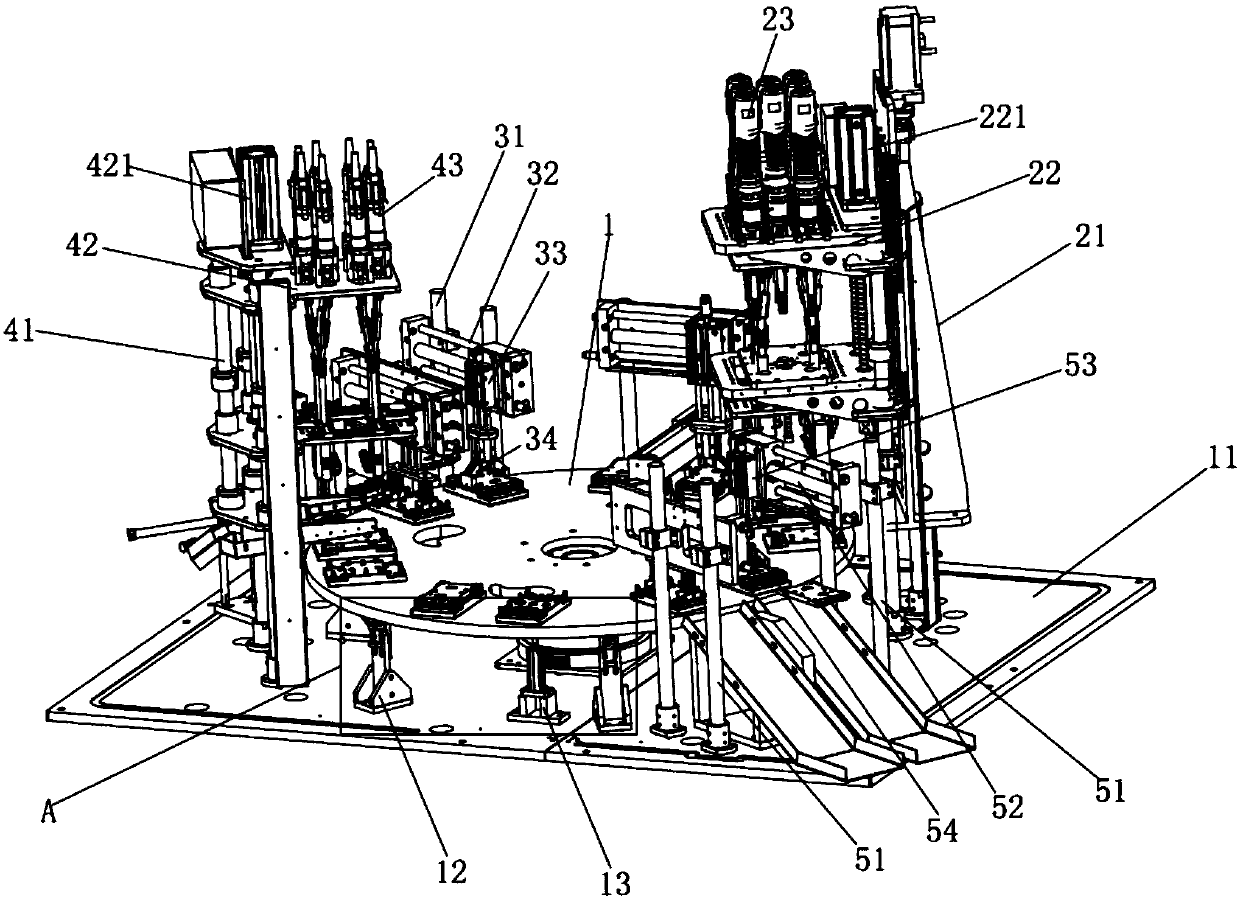
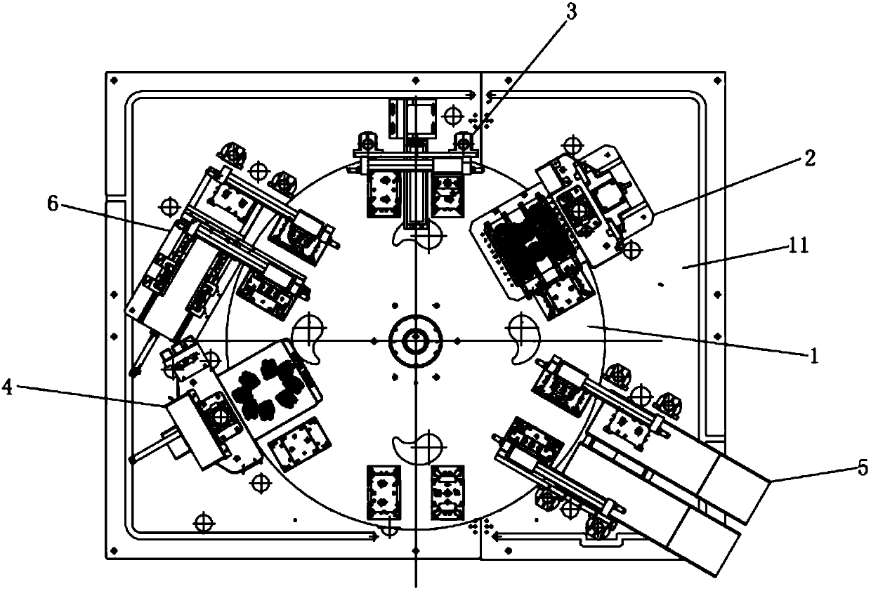
[0023] see Figure 1 to Figure 4 , the figure shows an automatic locking screw machine provided by Embodiment 1 of the present invention, which includes a turntable 1, which is rotatably mounted on a base 11, and a first lock surrounding the turntable 1 is fixedly installed on the base 11 Screw mechanism 2, first loading and unloading mechanism 3, second locking screw mechanism 4 and second loading and unloading mechanism 5, first locking screw mechanism 2, first loading and unloading mechanism 3, second locking screw mechanism 4 and second loading and unloading mechanism Mechanisms 5 are sequentially arranged clockwise or counterclockwise along the turntable 1, and a plurality of first guide mechanisms 12 are fixedly installed between the base 11 and the turntable 1, and the plurality of first guide mechanisms 12 are arranged along the circumferential direction of the turntable 1. Arranged equidistantly, the first guide mechanism 12 includes a first base 121 fixedly installed...

Embodiment 2

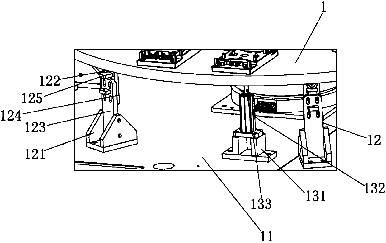
[0026] see Figure 1 to Figure 4 , the figure shows an automatic screw locking machine provided by Embodiment 2 of the present invention. On the basis of the above-mentioned embodiments, this embodiment further makes the following technical solutions as improvements: the first guide roller 122 Move back and forth on the first base 121 in the vertical direction; Specifically, the first mounting plate 123 arranged along the vertical direction is fixedly installed on the first base 121, and the second mounting plate 123 is slidably connected to the first mounting plate 123. 124 , the top of the second mounting plate 124 is rotatably connected with the first guide roller 122 . Through the setting of the above structure, the self-adaptive adjustment of the height of the first guide roller with respect to the turntable can be realized.

Embodiment 3

[0028] see Figure 1 to Figure 4 , the figure shows an automatic locking screw machine provided by Embodiment 3 of the present invention. On the basis of the above-mentioned embodiments, this embodiment further makes the following technical solutions as improvements: the second mounting plate 124 A guide plate 125 arranged horizontally is fixedly connected to the top, and the surface of the first guide roller 122 contacts the surface of the guide plate 125 .


PUM


Abstract

The invention provides an automatic screw locking machine which comprises a rotary disc rotationally installed on a base table. A first screw locking mechanism, a first feeding and discharging mechanism, a second screw locking mechanism and a second feeding and discharging mechanism which surround the rotary disc are fixedly installed on the base table, the first screw locking mechanism, the firstfeeding and discharging mechanism, the second screw locking mechanism and the second feeding and discharging mechanism are sequentially arranged clockwise or anticlockwise along the rotary disc, a plurality of first guide mechanisms are further fixedly installed between the base table and the rotary disc, and the first guide mechanisms are arranged in the circumferential direction of the rotary disc at equal intervals; and each first guide mechanism comprises a first base fixedly installed on the base table and a first guide roller installed on the first base, and the surface of the first guide roller makes contact with the bottom face of the rotary disc. By means of the automatic screw locking machine, the problem of the low product yield caused by rotation deviation of a rotary table inthe prior art can be effectively solved.

Description

technical field [0001] The invention relates to a screw locking machine, in particular to an automatic screw locking machine. Background technique [0002] For some jigs, it is sometimes necessary to fix the product on the jig with screws when inspecting the product. Now the screws are all manually screwed. There is an obvious disadvantage in operation efficiency, and it is not suitable for the use of mass production. [0003] In the later period, some screw-driving automation equipment was also applied. However, most of these screw-driving equipment switch and turn over materials between different stations through the turntable, and certain rotation deviations are prone to occur during the turntable process. For the screw locking operation of some small parts, it will cause errors in product installation accuracy and affect product yield. Contents of the invention [0004] In view of this, the present invention provides an automatic screw locking machine, which can effec...

Claims


Application Information

Patent Timeline
Patent Type & Authority Applications(China)
IPC IPC(8): B23P19/06
CPCB23P19/001B23P19/069
Inventor 李海亮
Owner 苏州意达诺精密科技有限公司
Features
  • R&D
  • Intellectual Property
  • Life Sciences
  • Materials
  • Tech Scout
  • Unparalleled Data Quality
  • Higher Quality Content
  • 60% Fewer Hallucinations
Learn More