Building timber cutting device

A cutting device and wood technology, applied in wood processing appliances, special forming/shaping machines, manufacturing tools, etc., can solve the problems of low cutting efficiency and inconvenient use.

Active Publication Date: 2020-07-07
安徽开路建筑工程有限公司
View PDF5 Cites 4 Cited by
  • Summary
  • Abstract
  • Description
  • Claims
  • Application Information

AI Technical Summary

Problems solved by technology

[0003] The existing wood cutting device can only cut a single time when cutting wood. When it is necessary to cut the round wood into the same length, it can...

Method used


Image

  • Building timber cutting device
  • Building timber cutting device
  • Building timber cutting device

Examples


Embodiment 1

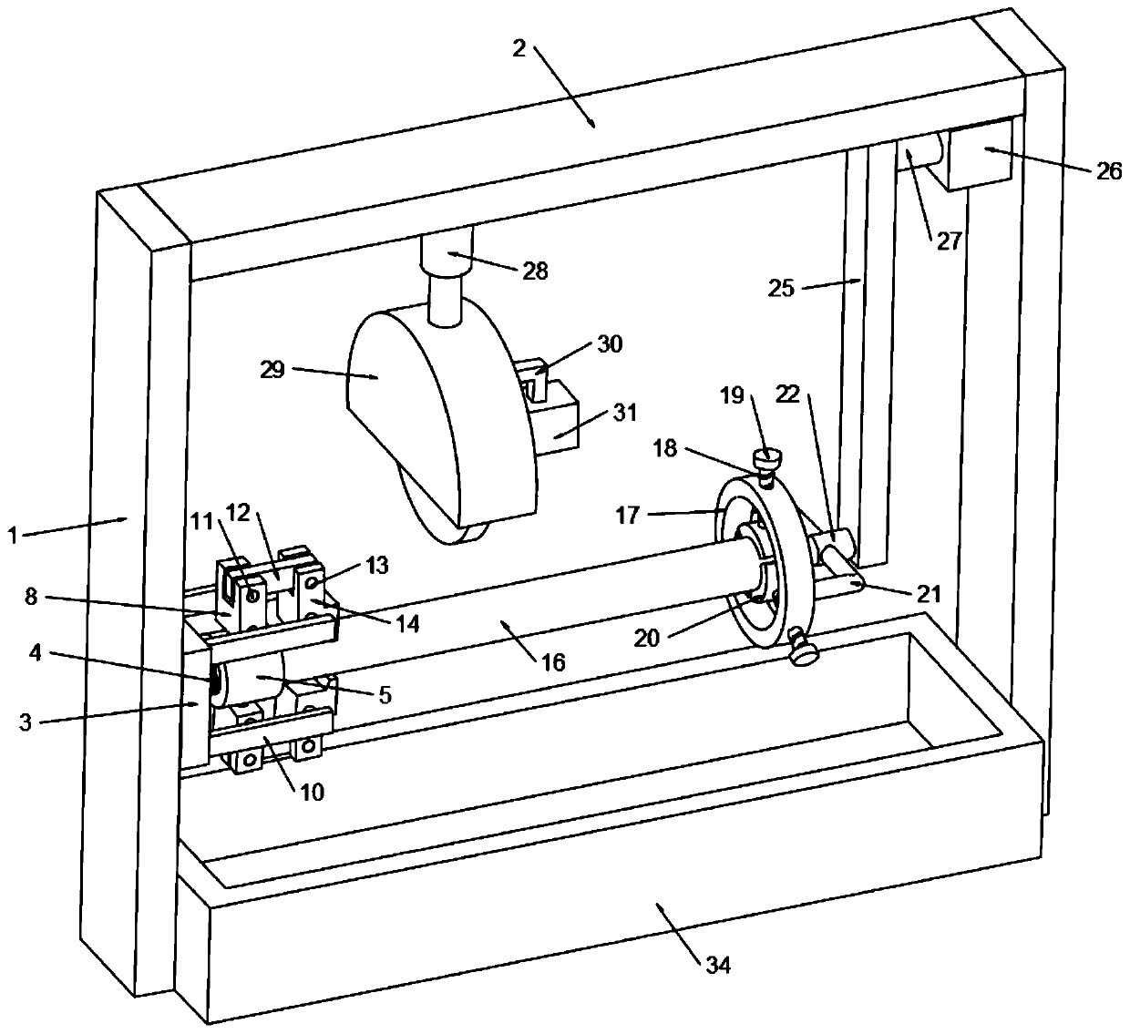
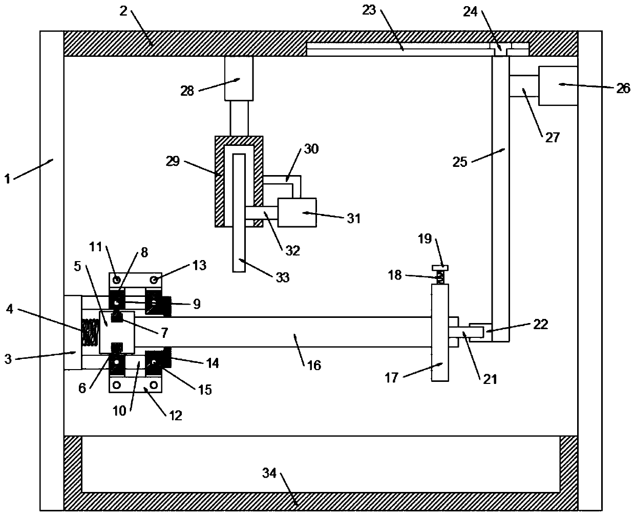
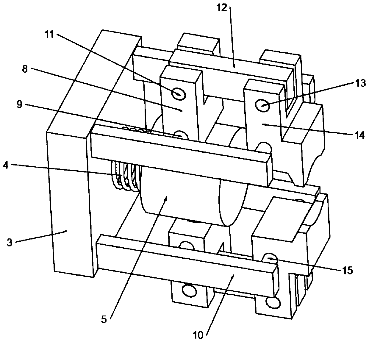
[0020] see Figure 1-3 , in an embodiment of the present invention, a construction timber cutting device includes a bracket 1, the upper end of the bracket 1 is fixedly connected with a top plate 2, the side wall of the bracket 1 on the left side is provided with a fixing seat 3, and the right side wall of the fixing seat 3 is A spring 4 is arranged on the top, and the end of the spring 4 is fixedly connected with a round table 5, and grooves 6 are arranged on the upper and lower side walls of the round table 5, and a boss 7 is installed in the groove 6, and the boss 7 is fixedly connected with a connecting block 8, and the connecting block 8 is hinged with a hinged shaft-9 near the end of the boss 7, the fixed seat 3 is provided with a fixed plate 10, the end of the hinged shaft-9 is fixedly connected on the fixed plate 10, and the end of the connecting block 8 away from the boss 7 is hinged with a Articulation shaft 2 11, articulation shaft 2 11 is rotatably connected with c...

Embodiment 2

[0027] In order to facilitate the collection of the cut round wood 16, this embodiment is further improved on the basis of Embodiment 1. The improvement is: a storage box 34 is arranged between the supports 1, and the storage box 34 is located at the fixed block 14 Directly below, the cut circular timber 16 falls off from the fixing block 14 and falls into the storage box 34 located directly below, which facilitates the collection and arrangement of the circular timber 16 and improves the convenience of the device.

[0028] The working principle of this embodiment is: in order to facilitate the collection of the cut round wood 16, a storage box 34 is arranged between the supports 1, the storage box 34 is located directly below the fixed block 14, and the cut round wood 16 16 falls off from the fixed block 14 and falls into the storage box 34 located directly below, which facilitates the collection and arrangement of the round timber 16 and improves the convenience of the device. ...


PUM


Abstract

The invention discloses a building timber cutting device which comprises a bracket. The upper end of the bracket is fixedly connected to a top plate, a fixed seat is arranged on the left bracket, a spring is arranged on the fixed seat, the tail end of the spring is fixedly connected to a circular truncated cone, a groove is formed in the circular truncated cone, a boss is mounted in the groove, the boss is fixedly connected to a connecting block, the connecting block is hinged to a hinge shaft I, a fixed plate is arranged on the fixed seat, the tail end of the hinge shaft I is fixedly connected to the fixed plate, the connecting block is hinged to a hinge shaft II, the hinge shaft II is rotatably connected to a connecting rod, the connecting rod is provided with a hinge shaft III, the hinge shaft III is rotatably connected to a fixed block, the fixed block is hinged to a hinge shaft IV, the hinge shaft IV is fixedly connected to the fixed plate, a round timber is arranged on the circular truncated cone, and a cutting device is arranged on the top plate and a clamping device is slidably mounted on the top plate. By arranging the circular truncated cone, the building timber cutting device can fix one end of a round timber automatically, so that the cut off timber is separated from the fixed block automatically and the timber is cut continuously.

Description

technical field [0001] The invention relates to the construction field, in particular to a construction timber cutting device. Background technique [0002] Wood is an important raw material and is widely used in the construction field. Wood processing is an important technological means. Efficient, fine and automated wood processing equipment has been actively researched, designed and produced. Among wood processing equipment, wood cutting equipment is being demanded in large quantities. In the processing of building wood, the wood is cut according to the different needs of the product. When cutting the wood, a wood cutting machine is needed to cut the wood into various specifications of the board through the wood cutting machine, so as to meet the processing needs. [0003] The existing wood cutting device can only cut a single time when cutting wood. When it is necessary to cut the round wood into the same length, it can only manually move the wood repeatedly and re-clam...

Claims


Application Information

Patent Timeline
IPC IPC(8): B27C5/00
CPCB27C5/00
Inventor 巴秀英
Owner 安徽开路建筑工程有限公司
Why Eureka
Try Eureka