Supercharge Your Innovation With Domain-Expert AI Agents!

Automatic locking device and usage method

A technology of automatic locking and locking blocks, which is applied in the direction of building locks, buildings, building structures, etc., and can solve problems such as locking that cannot be automated and that cannot meet the requirements of use

Active Publication Date: 2021-05-04
CHINA THREE GORGES UNIV
View PDF4 Cites 0 Cited by
  • Summary
  • Abstract
  • Description
  • Claims
  • Application Information

AI Technical Summary

Problems solved by technology

[0002] At present, the usual locking device adopts a bolt locking mechanism. The locking mechanism of the above structure needs to be locked manually during the locking process, and automatic locking cannot be realized. In some special applications Occasionally it cannot meet the requirements of use

Method used


Image

  • Automatic locking device and usage method
  • Automatic locking device and usage method
  • Automatic locking device and usage method

Examples


Embodiment 1

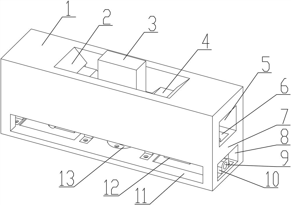
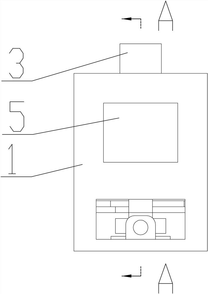
[0035] see Figure 1-6 , an automatic locking device, which includes an outer shell 1, the top of the outer shell 1 is processed with a tapered inlet 2; the middle part of the outer shell 1 is processed with a through hole 5 through its length direction, and the outer shell 1 The bottom layer of 1 is processed with a connecting rod mechanism installation groove 11, and an intermediate partition 23 is formed between the connecting rod installation groove 11 and the through hole 5, and the two sides of the intermediate partition 23 are symmetrically processed with chute 6, and the A locking block 21 is installed slidingly on the chute 6, and a reset mechanism is arranged between the locking block 21 and the outer shell 1, and the locking block 21 and the lock head block 3 form a hook locking fit; The locking block 21 cooperates with the synchronous link mechanism installed inside the connecting mechanism installation groove 11, and drives it to slide along the chute 6, so as to ...

Embodiment 2

[0045] The method of using the automatic locking device includes the following steps:

[0046] Step 1: The two locking blocks 21 are located at the innermost end of the chute 6 under the action of the return spring 19;

[0047] Step 2: Push the lock block 3 into the inside of the through hole 5 along the tapered inlet 2, the tapered structure 22 will push the locking block 21 to slide to both ends, and when it slides to the right end, the locking block 21 will Press-fit on the top of the tapered structure 22 to complete the locking of the lock block 3;

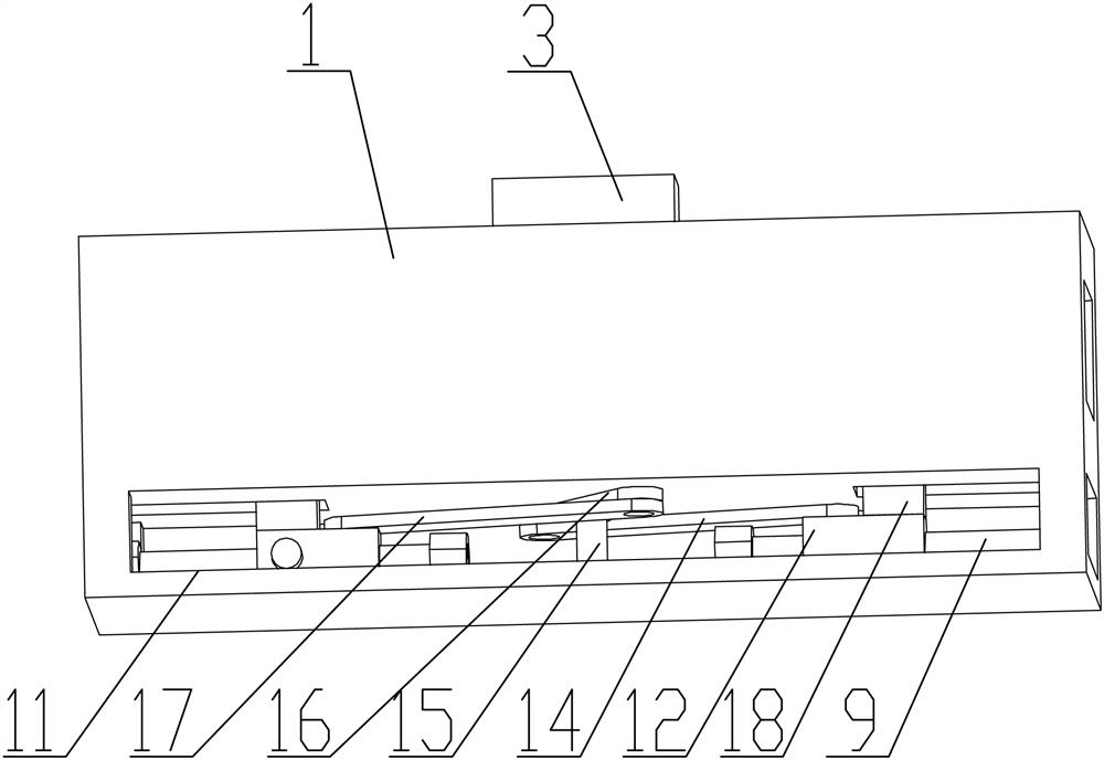
[0048] Step 3: When the lock needs to be released, drive the rotating shaft 15 to rotate through the power device, drive the rotating arm 16 to rotate through the rotating shaft 15, and then drive the first connecting rod 14 and the second connecting rod 17 synchronously through the rotating arm 16, and pass the first connecting rod The rod 14 and the second connecting rod 17 synchronously drive the slider 12 to slide along t...


PUM


Abstract

The invention provides an automatic locking device and a method for using it. It comprises an outer casing, the top of the outer casing is processed with a tapered inlet; the middle part of the outer casing is processed with a through hole through its length direction. The bottom layer of the body is processed with a connecting rod mechanism installation groove, and a middle partition is formed between the connecting rod mechanism installation groove and the through hole, and the two sides of the middle partition are symmetrically processed with chute, and the sliding fit is installed on the chute. There is a locking block, and a reset mechanism is arranged between the locking block and the outer shell, and the locking block and the lock block form a hook and locking fit; the locking block is installed in the installation groove of the connecting mechanism. The synchronous link mechanism cooperates and drives it to slide along the chute to realize the locking and releasing functions. The automatic locking device can realize the automatic locking function, thereby satisfying the use requirement of self-locking.

Description

technical field [0001] The invention belongs to the field of locking devices, in particular to an automatic locking device and a use method. Background technique [0002] At present, the usual locking device adopts a bolt locking mechanism. The locking mechanism of the above structure needs to be locked manually during the locking process, and automatic locking cannot be realized. In some special applications Occasionally it cannot meet the requirements of use. Contents of the invention [0003] In order to solve the above technical problems, the present invention provides an automatic locking device and a method of use. The automatic locking device can realize the automatic locking function, thereby satisfying the use requirements of self-locking. [0004] In order to achieve the above-mentioned technical features, the object of the present invention is achieved as follows: an automatic locking device, which includes an outer casing, the top of the outer casing is proces...

Claims


Application Information

Patent Timeline
Patent Type & Authority Patents(China)
IPC IPC(8): E05B15/00E05B15/02E05B15/10
CPCE05B15/00E05B15/022E05B15/10
Inventor 艾伟李立军熊晓晨
Owner CHINA THREE GORGES UNIV
Features
  • R&D
  • Intellectual Property
  • Life Sciences
  • Materials
  • Tech Scout
  • Unparalleled Data Quality
  • Higher Quality Content
  • 60% Fewer Hallucinations
Learn More