Measuring system and measuring method considering focusing and leveling and precision alignment

A measurement system, focusing and leveling technology, applied in the field of lithography machines, can solve the problems of long production time, high space occupancy rate of lithography machines, and low yield of lithography machines

Active Publication Date: 2020-07-07
INST OF OPTICS & ELECTRONICS - CHINESE ACAD OF SCI
12 Cites 4 Cited by

AI-Extracted Technical Summary

Problems solved by technology

[0004] The technical problem to be solved by the present invention is to provide a measurement system and measurement method that takes into account both focus adjustment, leveling and precision alignment, so as to solve the problems caused by the independent vertical and horizontal detection systems in the existing photolithography machines. For the problem of...

Method used

With reference to Fig. 1, this measurement system comprises six degrees of freedom nano-motion stage 1; Carrier stage 2, is installed on the six-degree-of-freedom nano-motion stage 1; Silicon wafer 3 to be exposed; Exposure mask 4, is clamped by mask The holding device 6 is fixed; the main substrate 5; the mask holding device 6 is fixed on the main substrate 5; the alignment mark 7 on the substrate; the gap measurement mark 8 on the mask; the alignment mark area 9 on the mask; Illumination light source lens 10; the first and second X\Y axis displacement stages 100\200; the first and second Tz axis rotation stages 101\201, respectively installed on the first and second X\Y axis displacement stages 100\200 top; the first and second tilting adapter plates 102\202 are respectively installed on the first and second Tz-axis rotary tables 101\201; the first and second Z-axis displacement tables 103\203 are connected with the first and second The two Tz-axis rotary tables 101\201 are respectively connected with the first and second Rx/Ry rotary tables 104\204 for focusing of the CCD camera; the first and second Rx/Ry rotary tables 104\204; the first and secon...

Abstract

The invention discloses a measuring system considering focusing and leveling and precision alignment and a measuring method thereof. The system is characterized in that a dark field moire fringe alignment deviation detection function and a chirped grating gap detection function are integrated into one group of detection units. According to the measurement system considering alignment and focusingleveling, an integrated structure of a vertical measurement system and a horizontal measurement system is realized, the space requirement of a photoetching machine complete machine system is reduced,and the space occupation rate of a photoetching machine is reduced. According to the measuring method of the measuring system considering alignment and focusing leveling, the focusing leveling and alignment of the substrate are achieved, and the working efficiency of a photoetching machine is improved.

Application Domain

Photomechanical treatment

Technology Topic

EngineeringGrating +1

Image

  • Measuring system and measuring method considering focusing and leveling and precision alignment
  • Measuring system and measuring method considering focusing and leveling and precision alignment
  • Measuring system and measuring method considering focusing and leveling and precision alignment

Examples

  • Experimental program(1)

Example Embodiment

[0024] In order to make the objectives, technical solutions, and device advantages of the present invention clearer, the present invention will be described in further detail below in conjunction with the accompanying drawings.
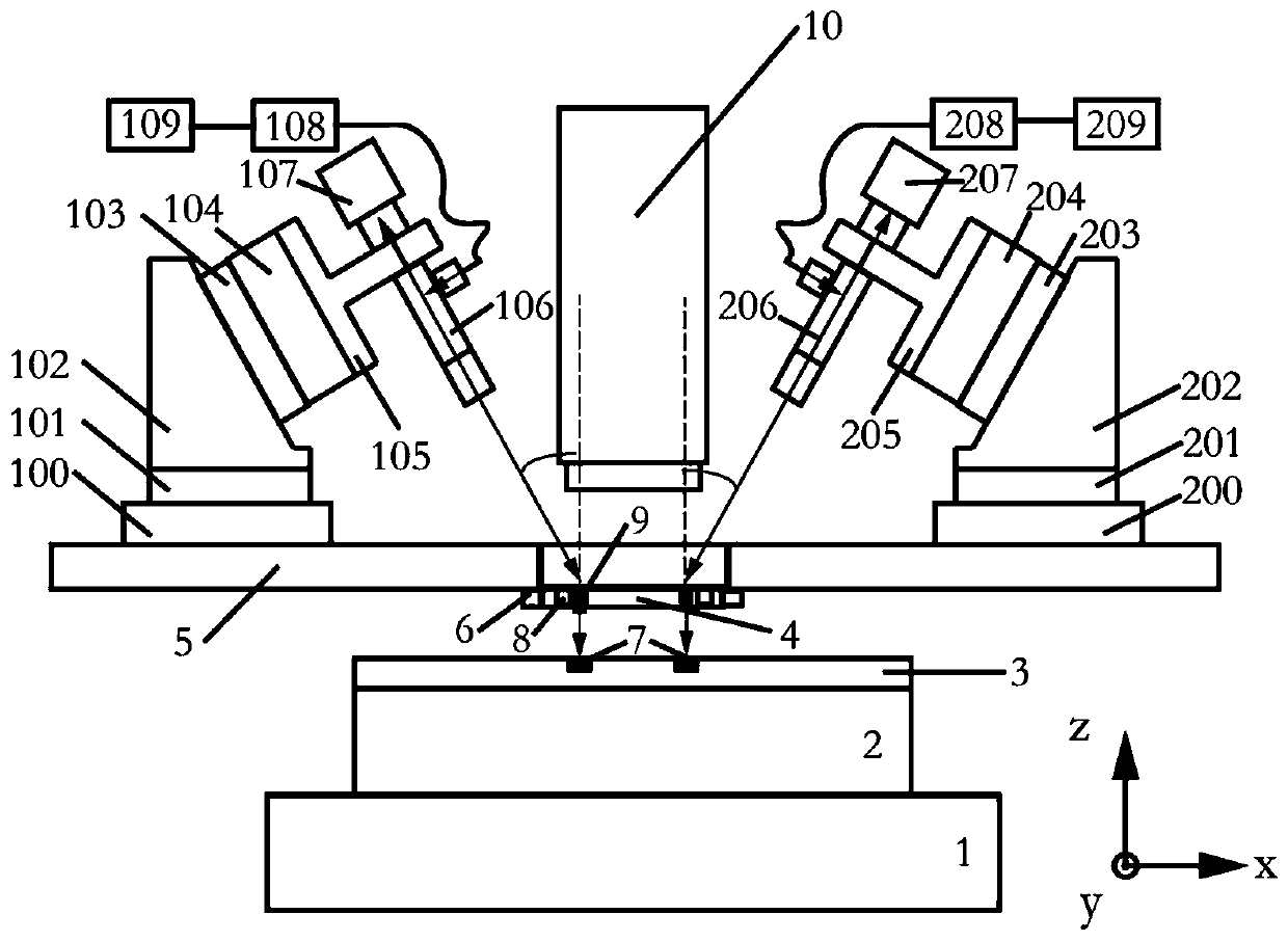
[0025] Reference figure 1 , The measurement system includes a six-degree-of-freedom nano-motion platform 1; a slide table 2, which is mounted on the six-degree-of-freedom nano-motion platform 1, a silicon wafer to be exposed 3; an exposure mask 4, which is fixed by a mask holding device 6; The substrate 5; the mask holding device 6 fixed to the main substrate 5; the alignment mark 7 on the substrate; the gap measurement mark 8 on the mask; the alignment mark area 9 on the mask; the illumination source lens 10; 1. The second X\Y axis translation stage 100\200; the first and second Tz axis rotation stages 101\201 are installed on the first and second X\Y axis translation stages 100\200; Two tilt adapter plates 102\202, respectively installed on the first and second Tz-axis rotation stages 101\201; the first and second Z-axis translation stages 103\203, and the first and second Tz-axis rotation stages 101 \201 is connected to the first and second Rx/Ry rotating stages 104\204, respectively, for focusing of CCD cameras; the first and second Rx/Ry rotating stages 104\204; the first and second lens holders 105\205, respectively used to fix the telecentric lens 106\206; the first and second telecentric lens 106\206; the first and second CCD camera 107\207, used for image acquisition; the first and second crystal oscillation The device 108\208 is used to eliminate the coherent characteristics of the laser; the first and second laser light sources 109\209. Among them, the same detection system is used for the gap value and alignment deviation value between the mask and the substrate, which reduces the space occupancy rate of the complete lithography machine and realizes online alignment deviation detection and gap value measurement.
[0026] Reference figure 2 , A lithography system based on the technology of the present invention, including 8 sets of the same alignment deviation detection module 10-1, 20-1, 30-1, 40-1, 50-1, 60-1, 70-1 and 80-1, respectively installed on the four corners of the graphics area, this layout is more conducive to detecting the alignment deviation of the journey image. Each set of alignment deviation detection module has the function of precise posture adjustment of the telecentric lens.
[0027] Refer to image 3 , The inspection system compatible with focusing, leveling and alignment includes X/Y-axis translation stage 100, Tz rotation stage 101, tilt adapter plate 102, Z-axis translation stage 103, Rx/Ry rotation stage 104, lens holder 105. Telecentric lens 106, CCD 107, crystal oscillator 108 and laser illumination light source 109.
[0028] Refer to Figure 4 , Is a feasible arrangement of the gap measurement mark and the alignment mark on the mask of the present invention. Alignment marks are arranged on the four corners of the entire pattern area. 4 sets of marks are used to measure the alignment deviation in the X direction, and the other 4 sets are used to measure the alignment deviation in the Y direction. The gap measurement marks are arranged next to the 4 sets of Y-direction alignment marks, and a suitable decoupling algorithm is designed to obtain the Z gap value between the mask and the substrate, and the yaw angle in the Rx and Ry directions. The left picture is the optical path diagram of the gap measurement. The light beam emitted by the laser light source passes through the crystal oscillator first to have coherence, and then the beam is irradiated to the gap measurement at an angle α with the normal direction of the mask after passing through the lens group beam expansion collimation module On the mark, after the diffraction of the chirped grating, the telecentric lens captures the interference image and images it on the CCD. Its design feature is that the laser beam irradiation angle is consistent with the diffraction imaging angle. The picture on the right is the alignment measurement optical path diagram. The light beam emitted by the laser light source passes through the crystal oscillator first to have coherence. Then, the light beam irradiates the alignment mark of the mask at an angle θ after passing through the mirror group beam expansion collimation module. The light beam diffracted by the grating on the mask irradiates the alignment image of the substrate, and forms a moiré image with a magnified period after being diffracted again. The image is captured by the telecentric lens and imaged on the CCD. Its characteristic is that the light beam is incident on the mask mark obliquely. On the one hand, it avoids interference with the spatial position of the illumination light source and realizes the online alignment deviation detection function. On the other hand, it only collects the diffraction order light of interest, which enhances Image contrast. In addition, designing the same angle for the aligning and irradiating angle and the irradiating angle of the gap measurement just makes the measurement system take into account the functions of alignment and focusing and leveling. In order to use a set of systems to balance focusing, leveling and alignment, the gap measurement beam incident angle here is equal to the incident angle of the counter-rotating beam. Among them, 3 is the silicon wafer; 4 is the mask; 8-1 is the first set of gap measurement marks; 8-2 is the second set of gap measurement marks; 8-3 is the third set of gap measurement marks; 8-4 is the first set of gap measurement marks Four sets of gap measurement marks; 9-1 is the first set of mask alignment marks; 9-2 is the second set of mask alignment marks; 9-3 is the third set of mask alignment marks; 9-4 is the first set of mask alignment marks Four sets of mask alignment marks; 9-5 is the fifth set of mask alignment marks; 9-6 is the sixth set of mask alignment marks; 9-7 is the seventh set of mask alignment marks; 9-8 Is the eighth group of mask alignment marks; 28 is the mask pattern area;
[0029] Refer to Figure 5 , Is the gap detection grating mark on the mask, the detection grating is composed of two groups of chirped gratings with reversed phases. The period of the detection grating in the X direction is fixed, but the period in the Y direction is not fixed. When a single-wavelength laser beam irradiates the detection mark at the designed Litro angle, the telecentric lens can collect interference patterns, including the left and right sets of interference patterns. When the gap between the mask and the substrate increases, a higher fringe frequency is produced; on the contrary, when the gap between the mask and the substrate decreases, the difference in the fringe period becomes smaller. The detection is not sensitive to whether the mask and the substrate are aligned, and does not require any pattern on the substrate, and can also be used in the exposure of the mark pattern of the 0th layer of the substrate. Using the spatial phase information of the left and right sets of interference fringes and adopting an accurate phase analysis method, the gap value on the order of nm can be obtained. Among them, 8-01 is the first set of mask gap measurement marks, used for gap measurement; 8-02 is the second set of mask gap measurement marks, used for gap measurement;
[0030] reference Image 6 , The picture on the left shows the detection of alignment deviation marks in the X direction. In this embodiment, the substrate X-direction moiré alignment mark 7-03 and the mask X-direction moiré alignment mark 7-03 are realized in the dark field environment Moiré fringe produced by 9-03 diffraction. The Moiré alignment mark 7-03 in the X direction of the substrate is designed as Image 6 The two-dimensional grating shown is a fine alignment mark on the substrate, and the mask X-direction moiré alignment mark 9-03 is designed as Image 6 The one-dimensional grating shown. The mask X-direction moiré alignment mark 9-03 is a diffraction grating having a period in the X direction, and the period is slightly different from the period in the second diffraction grating. The substrate X-direction moiré alignment mark 7-03 is a diffraction grating having periods in the X direction and the Y direction. At the same time, a diffraction grating with a moiré period in the Y direction (the substrate Y-direction moiré alignment mark 7-01 and the mask Y-direction moiré alignment mark 9-01) are respectively arranged on the mask and the substrate. , Used to extend the detection range of the Moiré fringe in the X direction. Image 6 On the right is the detection of the alignment deviation mark in the Y direction, which realizes the moiré produced by the diffraction of the substrate Y-direction moiré alignment mark 7-01 and the mask Y-direction moiré alignment mark 9-01 in the dark field environment Stripes, set one to Image 6 The diffraction grating shown on the right, and the substrate Y-direction Moiré alignment mark 7-01 is set as Image 6 The diffraction grating with a two-dimensional structure is shown on the right. The mask Y-direction moiré alignment mark 9-01 is a diffraction grating having a period in the Y direction, which is a period different from the period in the second diffraction grating. The substrate Y direction moiré alignment mark 7-01 is a diffraction grating having periods in the Y direction and the X direction. In addition, the mask Y-direction coarse alignment mark 9-00 and the substrate Y-direction coarse alignment mark 7-00 are used for coarse alignment in the Y direction to expand the detection range of the moiré. Note that the first direction and the second direction are not limited to being arranged perpendicular to each other. In this embodiment, the magnification of the Moiré fringe:
[0031]
[0032] reference figure 1 , figure 2 , image 3 , Figure 4 with Figure 5 , The operation process of the detection system is as follows:
[0033] Step 1: Power on reset, adjust the posture of the telecentric lens through the 6-DOF motion stage, so that the collimated measurement beam is incident on the center area of ​​the gap measurement mark and alignment mark of the mask at a litero angle to ensure that the CCD can be simultaneously Collect gap measurement interference image and align interference image;
[0034] Step 2: Adjust the Z-axis position of the moving platform to focus the CCD lens, collect the diffraction image of the chirped grating, and analyze the frequency distribution of fringes and the phase difference between the left and right groups of fringes based on the spatial phase analysis method, and then calculate the test The vertical gap value between the upper surface of the substrate and the lower surface of the mask; at the same time, the moiré pattern formed by diffraction of the mask alignment mark and the substrate alignment mark is collected, and based on a similar spatial phase method, the left and right directions to be measured are analyzed The phase values ​​of the two sets of coarse and fine stripes are used to calculate the horizontal alignment deviation between the mask and the substrate to be tested.
[0035] Step 3: Utilize 4 sets of gap measurement values ​​on the mask and use the geometric change method to obtain the positional relationship between the substrate and the mask, including the vertical gap value, Rx and Ry yaw angle and other information. A substrate focusing and leveling control system with vertical gap value, Rx and Ry yaw angles as feedback signals and nano-motion as the actuator is established to realize the focus and leveling operation of the mask and the substrate.
[0036] Step 4: Use the 8 sets of alignment marks on the mask and the substrate to calculate the alignment deviation value between the mask and the substrate; establish a substrate alignment control system with the alignment deviation as a feedback signal, and adjust the substrate through the nano-motion stage The posture of the film in the horizontal direction realizes the alignment operation of the mask and the substrate.
[0037] The above are only specific embodiments of the present invention, but the protection scope of the present invention is not limited thereto. Anyone familiar with the technology within the scope of the technology disclosed in the present invention can understand that conceivable changes or substitutions are all covered by the scope of the present invention. Therefore, the protection scope of the present invention should be subject to the protection scope of the claims.

PUM

no PUM

Description & Claims & Application Information

We can also present the details of the Description, Claims and Application information to help users get a comprehensive understanding of the technical details of the patent, such as background art, summary of invention, brief description of drawings, description of embodiments, and other original content. On the other hand, users can also determine the specific scope of protection of the technology through the list of claims; as well as understand the changes in the life cycle of the technology with the presentation of the patent timeline. Login to view more.
Why Eureka
Try Eureka