Combined clamp

A technology of combining fixtures and positioning bottom plates, which is applied in the field of tooling and fixtures, to improve product quality and yield, solve processing tool vibration, and reduce production costs.

Inactive Publication Date: 2020-07-10
ZHUHAI RUNXINGTAI ELECTRICAL
View PDF6 Cites 4 Cited by
  • Summary
  • Abstract
  • Description
  • Claims
  • Application Information

AI Technical Summary

Problems solved by technology

[0003] The present invention aims to solve the problems described above

Method used


Image

  • Combined clamp

Examples


Embodiment Construction

[0014] In order to make the purpose, technical solutions and advantages of the embodiments of the present invention clearer, the technical solutions in the embodiments of the present invention will be clearly and completely described below in conjunction with the drawings in the embodiments of the present invention. Obviously, the described embodiments It is a part of embodiments of the present invention, but not all embodiments. Based on the embodiments of the present invention, all other embodiments obtained by persons of ordinary skill in the art without making creative efforts belong to the protection scope of the present invention. It should be noted that, in the case of no conflict, the embodiments in the present application and the features in the embodiments can be combined arbitrarily with each other.

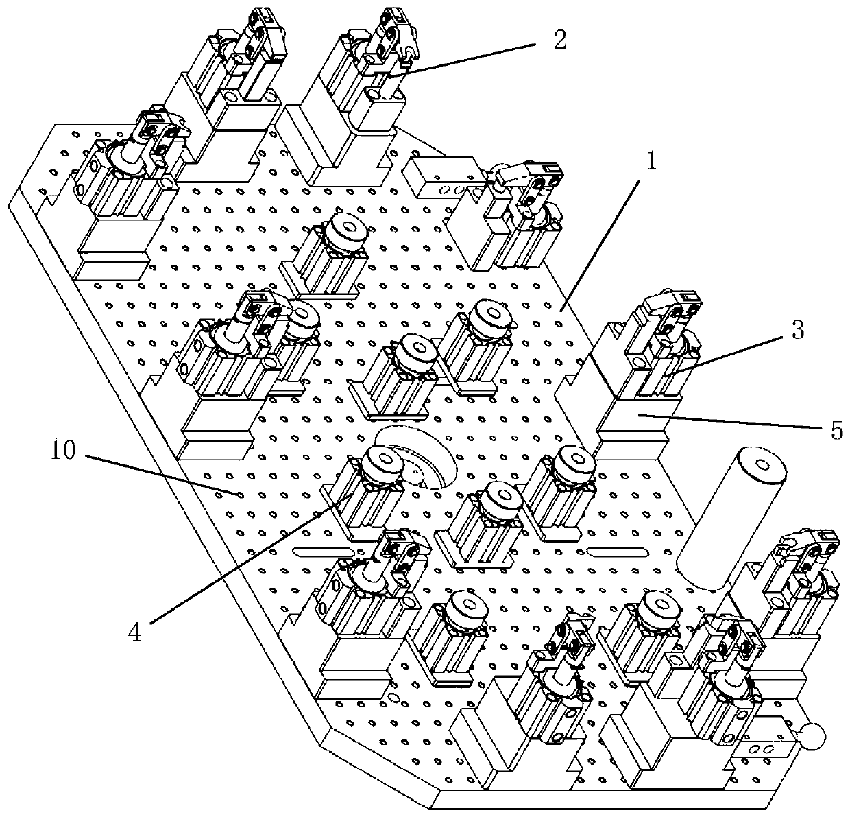
[0015] The inventor arranges a number of mounting holes in an array at equal intervals on the positioning base plate for the fixed installation of the positioning pin ...


PUM


Abstract

The invention provides a combined clamp. The combined clamp comprises a locating base plate, multiple locating pin press bases and multiple locating face press bases. Multiple installation holes are formed in the locating base plate in an array mode at equal intervals, the locating pin press bases are detachably installed on the locating base plate through the installation holes, and the locatingface press bases are detachably installed on the locating base plate through the installation holes. According to the combined clamp, the positions of the locating pin press bases and the locating face press bases can be adjusted according to products with different shapes and specifications, and therefore the application range of the combined clamp can be effectively broadened, the service life can be prolonged, and the production cost can be reduced; and supporting air cylinders with air control valves are utilized to support the suspended portion of a product to be processed, and thereforethe product is prevented against clamping deformation, the problem of machining cutter vibration is effectively solved, and the product quality and the yield are improved.

Description

technical field [0001] The invention relates to the technical field of tooling fixtures, in particular to a combination fixture. Background technique [0002] The existing communication housing fixtures can only be clamped and produced for a single part, and the housing is replaced quickly, with many product part numbers and similar appearances, but it is difficult to overlap the positions of the specific positioning pins, and the housing is large in size, resulting in There are many problems such as large volume of the body clamp, short production cycle of a single part drawing number, large area occupied by the fixture, and high cost. The existing fixture is used in production. In order to reduce the unit production time, the back cutting amount of the inner cavity of the shell is 0.8 to 2.5 mm. When the back cutting amount exceeds 1.0 mm, it is easy to produce vibration lines, resulting in the surface of the inner cavity of the workpiece. Unqualified roughness will serio...

Claims


Application Information

Patent Timeline
Patent Type & Authority Applications(China)
IPC IPC(8): B25B11/00
CPCB25B11/00
Inventor 任怀德孙立君张莹
Owner ZHUHAI RUNXINGTAI ELECTRICAL
Why Eureka
Try Eureka