

Flexible pneumatic arm for intelligent manufacturing equipment
An intelligent manufacturing and flexible technology, which is applied in the direction of manufacturing tools, program control manipulators, chucks, etc., can solve the problems of inability to form bifurcations, and achieve good stability and flexible and diverse forms of use.
- Summary
- Abstract
- Description
- Claims
- Application Information
AI Technical Summary
Problems solved by technology
Method used
Image

Examples
Embodiment 1
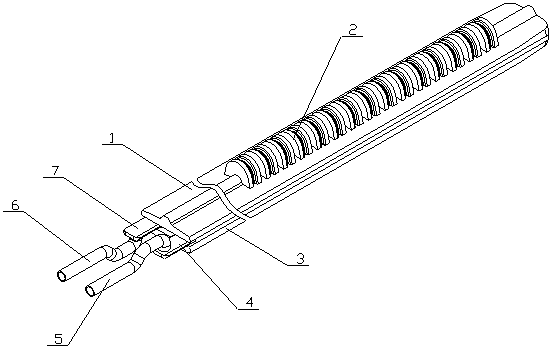
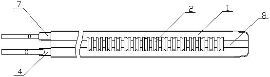
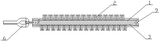
[0024] A flexible pneumatic arm for intelligent manufacturing equipment of the present invention is realized in the following way: a flexible pneumatic arm for intelligent manufacturing equipment of the present invention consists of an upper clamping part (1), a telescopic part (2), a lower clamping part (3), Composed of upper connecting tube (4), upper trachea (5), lower trachea (6), lower connecting tube (7), reinforced air ribs (8), fixed buckle (9) and sealed intubation tube (10), the upper clip The holding part (1) is located above the lower clamping part (3), and the fixed hasp (9) is placed between one end of the upper clamping part (1) and one end of the lower clamping part (3), and the fixed hasp (9) ) to connect one end of the upper clamping part (1) and one end of the lower clamping part (3), both of the upper clamping part (1) and the lower clamping part (3) are hollow structures, and the upper clamping part (1) ) The middle part of the upper side is arched upwards...
Embodiment 2
[0028] The difference between this embodiment and the other embodiments is: the telescopic part (2) is in an inclined state; when in use, when the upper air pipe (5) or the lower air pipe (6) is inflated or pumped, the upper clamping part (1 ) or the lower clamping part (3) for spiral curling, the hooking effect is better and the fixation is stable;
[0029] The design of the reinforced air ribs (8) makes the connection between the upper clamping part (1) and the lower clamping part (3) to the telescopic part (2) stable, and the curling effect is good;
[0030] The seal cannula (10) is designed with a sealing gasket to enhance the sealing of the seal cannula (10) and the upper clamping part (1) and the lower clamping part (3), and the suction effect is good;
[0031] The telescoping part (2) is designed with an arc-shaped groove, which is convenient for the telescopic part (2) to expand or collapse, so as to curl the upper clamping part (1) and the lower clamping part (3);
[0...
PUM
 Abstract
Description
Claims
Application Information