
Enveloping under-actuated robot gripper

A robotic hand and underactuated technology, which is applied in the field of robot gripper devices and underactuated robot grippers, can solve the problems of complex drive structure, small envelope range, and inflexibility, etc., and achieve simplified gripper structure and large grasping range , cost reduction effect

Active Publication Date: 2020-07-10
SHANGHAI UNIV
View PDF5 Cites 3 Cited by
  • Summary
  • Abstract
  • Description
  • Claims
  • Application Information

AI Technical Summary

Problems solved by technology

However, at present, the envelope range of the underactuated mechanical structure is small, the driving structure is complex, not flexible enough, and the efficiency is not high, which limits the application of underactuated machinery.

Method used


Image

  • Enveloping under-actuated robot gripper
  • Enveloping under-actuated robot gripper
  • Enveloping under-actuated robot gripper

Examples


Embodiment 1

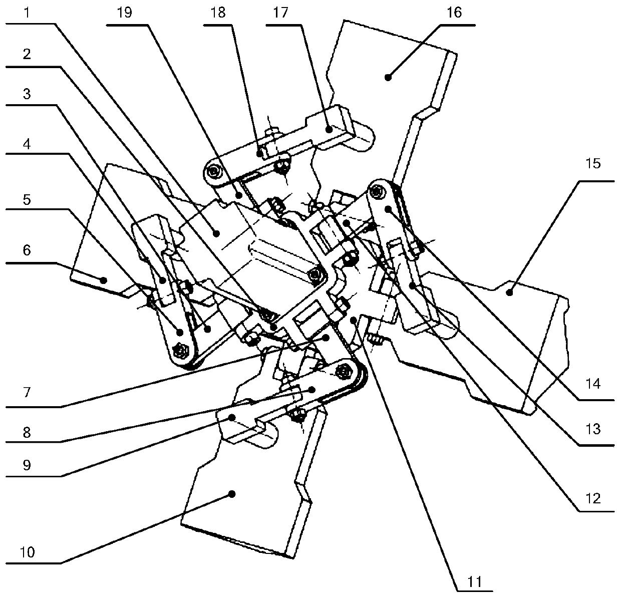
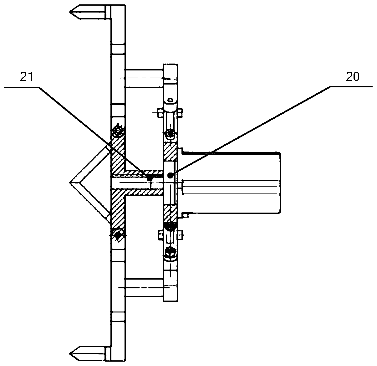
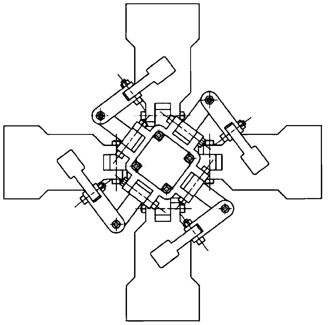
[0033] In this example, see Figure 1-Figure 5 , an envelope-type underactuated robot gripper, which includes a drive motor 1, a drive base 2, an envelope-type robot gripper structure composed of four finger units, a movable base 11, and a drive pad 20 And connection key 21; wherein the first finger unit includes the first drive seat connecting rod 3, the first receiving link 5, the first jaw connecting rod 4, the first claw plate 6; the second finger unit includes the second drive seat connecting rod Rod 7, second connecting rod 8, second jaw connecting rod 9, second jaw plate 10; the third finger unit includes third driving seat connecting rod 12, third receiving connecting rod 14, third jaw connecting rod 13. The third claw plate 15; the fourth finger unit includes the fourth drive seat connecting rod 19, the fourth connecting rod 18, the fourth jaw connecting rod 17, and the fourth claw plate 16; the driving motor 1 is the power source, which can A torque is provided to d...

Embodiment 2

[0046] This embodiment is basically the same as Embodiment 1, especially in that:

[0047] In this embodiment, the envelope-type underactuated robot gripper of this embodiment is used for mounting on a carrier platform, especially on a mechanical arm, for fixing. The enveloping underactuated robotic gripper in this embodiment has a wide range of uses, and can realize the opening and closing of the gripper with one driving source. The base platform is required to be assembled and fixed with the drive motor. The above functions ensure the advantages of low cost, energy saving, flexibility and light weight.

[0048] Based on the above embodiments, it can be seen that the envelope-type underactuated robot gripper can solve the problems of the existing mechanical robot grippers such as large movement stroke, complex mechanism, and large number of parts. It includes a driving motor, a base, a driving seat, a driving spacer, a connection key between the motor and the movable base, f...


PUM


Abstract

The invention discloses an enveloping under-actuated robot gripper. The enveloping under-actuated robot gripper can solve the problems that an existing mechanical robot gripper has large movement stroke, a complex mechanism, and large number of parts. The enveloping under-actuated robot gripper comprises a driving motor, a base, a driving seat, a driving pad, a connecting key for a motor and a movable base, four claw plates, four connecting rod kinematic chains for connecting the claw plates and the driving seat, a driving seat connecting rod, a bearing connecting rod, and a clamping jaw connecting rod, wherein the driving seat and the driving pad are fixedly connected to the driving motor to form a first-level fixing mechanism; and the moving base and the four claw plates are connected toform a second-level moving mechanism. When the gripper works, the rotation movement of the driving motor is transferred to the second-level moving mechanism through the connecting key to realize theenveloping and unfolding of the moving gripper. The connecting rod kinematic chains use the direction change of the rotation axis to ensure that the distance between two levels of platforms remains unchanged, and can convert 6 degrees of freedom into 1 degree of freedom. The enveloping under-actuated robot gripper has a simple and reliable structure, clever configuration, and few driving sources,and is suitable for application scenarios such as grabbing and picking of fruits and vegetables.

Description

technical field [0001] The invention relates to a robot gripper device, in particular to an underactuated robot gripper, which is applied in the technical field of robot equipment. Background technique [0002] Different grasping objects have different sizes and shapes, which requires that the manipulator should have good adaptability. Adaptability is mainly reflected in the following two aspects: one is to realize the grasping of objects of different sizes through the passive bending of the multi-stage claw joint; the other is to realize the clamping or clamping of the grasped objects by forming a certain range of closed envelope space Overall envelope. At the same time, the end effector of the robotic arm needs to have the functions of accurate, convenient and safe pick and place. For a long time, mechanical end effectors generally use the change of the distance between the two platforms to cooperate with the parallel linkage mechanism to realize the retraction and retra...

Claims


Application Information

Patent Timeline
Patent Type & Authority Applications(China)
IPC IPC(8): B25J15/02B25J15/10
CPCB25J15/022B25J15/10
Inventor 何斌张东薛豪俊徐辅泽张健滔
Owner SHANGHAI UNIV
Learn More