
Assembled building truss structure

A truss structure and prefabricated technology, which is applied in building construction and construction, can solve the problems of high production cost, high difficulty and high precision requirements, and achieves improved controllability and stability, reduced production cost and flexible operation. handy effect

Inactive Publication Date: 2020-07-10
王克峰
View PDF6 Cites 3 Cited by
  • Summary
  • Abstract
  • Description
  • Claims
  • Application Information

AI Technical Summary

Problems solved by technology

[0005] The invention provides a prefabricated building truss structure, which is simple to assemble, can be fine-tuned according to the actual installation situation, has high installation accuracy and stability, is easy to disassemble, and can effectively reduce the truss for some non-permanent construction projects. The advantage of production cost solves the problem that the existing building trusses are all welded during production, which is difficult and requires high precision, and it cannot be adjusted after the welding is completed. Once the deviation is large It will lead to the failure of normal assembly of the entire building truss, which is time-consuming and laborious, and the work efficiency is low. At the same time, the building truss of the welded structure is a permanent project. The problem of high production cost

Method used


Image

  • Assembled building truss structure
  • Assembled building truss structure
  • Assembled building truss structure

Examples


Embodiment Construction

[0029] The following will clearly and completely describe the technical solutions in the embodiments of the present invention with reference to the accompanying drawings in the embodiments of the present invention. Obviously, the described embodiments are only some, not all, embodiments of the present invention. Based on the embodiments of the present invention, all other embodiments obtained by persons of ordinary skill in the art without making creative efforts belong to the protection scope of the present invention.

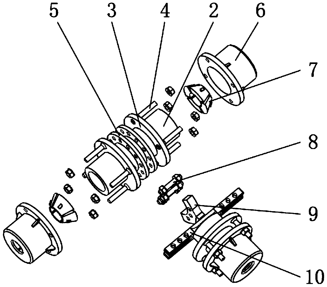
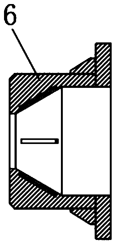
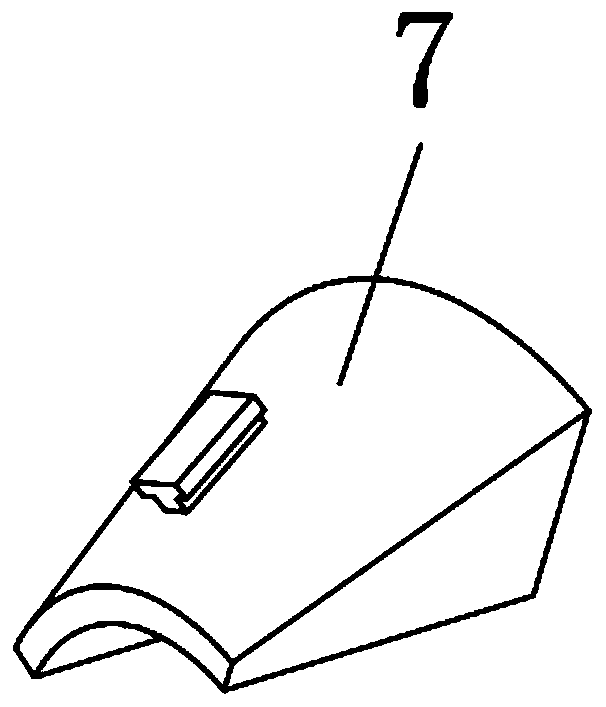
[0030] see Figure 1-7 , a prefabricated building truss structure, comprising a truss connecting rod 1, a fixing sleeve 2 is arranged on the outer surface of the truss connecting rod 1, and a fixing clamp 3 is fixedly installed on the upper and lower sides of the outer surface of the fixing sleeve 2, and the fixing clamp The outer edge of the plate 3 is provided with an adjusting screw 4, the middle part of the outer surface of the fixed sleeve 2 and between t...


PUM


Abstract

The invention relates to the technical field of building engineering equipment, and discloses an assembled building truss structure which comprises a truss connecting rod. A fixed sleeve is arranged on the outer surface of the truss connecting rod, fixed clamping plates are fixedly arranged on the upper side and the lower side of the outer surface of the fixed sleeve, a mounting flange plate is arranged in the middle of the outer surface of the fixed sleeve and located between the two groups of fixed clamping plates, and a movable pressing sleeve is fixedly arranged on the outer surface of anadjusting screw rod through a nut. A movable pressing tongue is movably sleeved with the movable pressing sleeve, and one end of the movable pressing tongue is in contact with one end of the fixed sleeve. According to the assembled building truss structure, as for the arrangement of an auxiliary support, auxiliary straight rods can be conveniently and flexibly arranged in the whole building trussstructure, so that a stable and effective triangular structural unit is formed, the stability of the assembled building truss structure and the rigidity of the whole truss structure are improved, andthe safety and the stability of the assembled building truss are effectively improved.

Description

technical field [0001] The invention relates to the technical field of construction engineering equipment, in particular to an assembled building truss structure. Background technique [0002] A building truss is a planar or spatial structure composed of straight rods and generally has a triangular unit structure. Increase the rigidity of its structure, and then act as a stable support structure for the roof of the building factory. [0003] At present, the existing building trusses are made by welding, and are installed on the supporting frame by means of fixed supports at both ends. However, the building trusses are generally large in size. If they are welded on the ground, the Assembly is difficult and requires high precision. It cannot be adjusted after the welding is completed. Once the deviation is large, the entire building truss cannot be assembled normally. It needs to be cut and re-welded, which is time-consuming It is laborious and the work efficiency is low. If...

Claims


Application Information

Patent Timeline
Patent Type & Authority Applications(China)
IPC IPC(8): E04B1/343E04B1/58
CPCE04B1/34326E04B1/58E04B2001/5875
Inventor 扣璇
Owner 王克峰
Learn More