[0020] The technical solutions in the embodiments of the present invention will be clearly and completely described below in conjunction with the accompanying drawings in the embodiments of the present invention. Obviously, the described embodiments are only a part of the embodiments of the present invention, rather than all the embodiments. Based on the embodiments of the present invention, all other embodiments obtained by those of ordinary skill in the art without creative work shall fall within the protection scope of the present invention.
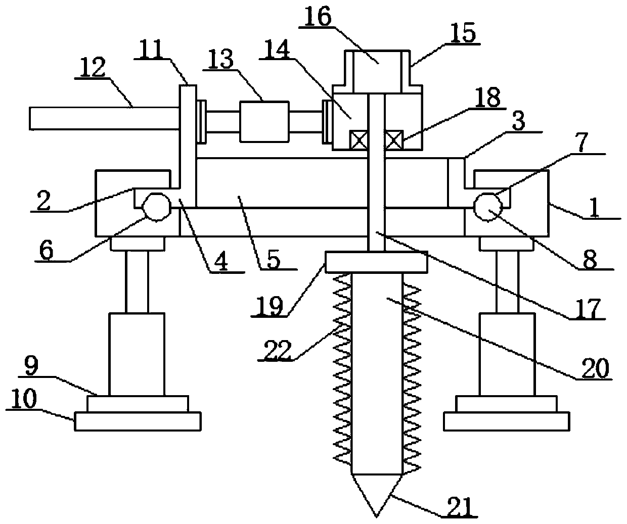
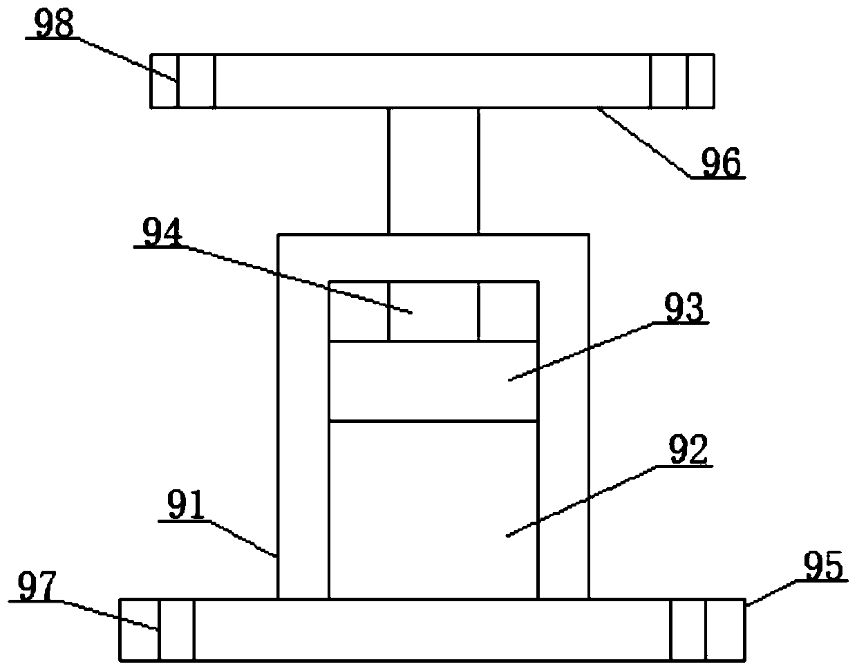
[0021] See figure 1 , An embodiment provided by the present invention includes an outer ring block 1, a plurality of bolt-mounted telescopic limit connection mechanisms 9 are installed at the bottom of the outer ring block 1, and each of the bolts is equipped with a telescopic limit connection mechanism 9 A main fixed base plate 10 is installed at the bottom of the outer ring block 1, an annular groove structure 2 is provided on the inner surface of the outer ring block 1, and a main ring body 4 is installed inside the ring groove structure 2, and the inner side of the main ring body 4 An integrated main circular plate 3 is provided on the top. The main circular plate 3 is provided with a transverse main groove hole structure 5 inside. The bottom surface of the main ring body 4 and the outer ring block 1 are located in the ring groove structure. 2 The bottom surface is provided with a top annular groove structure 7 and a bottom annular groove structure 6 respectively. A plurality of balls 8 are placed inside the top annular groove structure 7 and the bottom annular groove structure 6 and the main circle The top of one side of the plate 3 is provided with a vertical plate structure 11, the vertical plate structure 11 is equipped with a manual rod 12 on the end surface facing the outside, and the vertical plate structure 11 is installed with a reverse thread structure rotation on the end surface facing the inside. Type transverse distance adjustment mechanism 13. One end of the reverse thread structure rotary type transverse distance adjustment mechanism 13 is installed with a main component mounting plate 14. The upper surface of the main component mounting plate 14 is mounted with a drive motor mounting housing 15. A drive motor 16 is installed inside the motor mounting housing 15. The motor spindle 17 of the drive motor 16 penetrates the main component mounting plate 14, and the two are fixedly connected between the penetration parts by the main bearing 18. The motor spindle The shaft body of 17 penetrates the main groove hole structure 5 and the outer ring block 1, and the bottom end of the motor main shaft 17 is equipped with a coil spring elastic resistance type maximum rotation intensity control mechanism 19, the coil spring elastic resistance type maximum A main rotating threaded column 20 is installed at the bottom end of the rotation strength control mechanism 19, the bottom end of the main rotating threaded column 20 is provided with a tip structure 21, and the side of the main rotating threaded column 20 is provided with a main external thread structure 22.
[0022] See figure 2 , The bolt-mounted telescopic limit connection mechanism 9 includes a hollow shell 91 for bolt-mounted telescopic limit connection mechanism, a hollow structure 92 for bolt-mounted telescopic limit connection mechanism, and a moving plate for bolt-mounted telescopic limit connection mechanism 93. Telescopic rod for bolt installation telescopic limit connection mechanism 94, bolt installation telescopic limit connection mechanism with first connecting plate 95, bolt installation telescopic limit connection mechanism with second connecting plate 96, bolt installation telescopic limit The first bolt hole 97 for the position connection mechanism and the second bolt hole 98 for the bolt installation telescopic limit connection mechanism; the hollow housing 91 for the bolt installation telescopic limit connection mechanism is provided with a bolt installation telescopic limit connection in the inner center The hollow structure 92 for the mechanism, the hollow shell 91 for the bolt-mounted telescopic limit connection mechanism is installed inside the hollow structure 92 for the bolt-mounted telescopic limit connection mechanism, and a bolt is installed for the movable telescopic limit connection mechanism Plate 93, the bolt-mounted telescopic limit connection mechanism is mounted on the top center of the movable plate 93 with a bolt-mounted telescopic rod 94 for the telescopic limit connection mechanism, and the bolt is mounted on the bottom of the hollow housing 91 for the telescopic limit connection mechanism The first connecting plate 95 for bolt-mounted telescopic limit connecting mechanism and the second connecting plate 96 for bolt-mounted telescopic limit connecting mechanism are respectively installed on the top end of the telescopic rod 94 for the bolt-mounted telescopic limit connection mechanism. The first connecting plate 95 for installing the telescopic limit connecting mechanism and the second connecting plate 96 for bolt installing the telescopic limit connecting mechanism are successively provided with a plurality of bolts for installing the telescopic limit connecting mechanism with first bolt holes 97 and The second bolt hole 98 for bolt installation telescopic limit connection mechanism; the first connecting plate 95 for bolt installation telescopic limit connection mechanism is inserted into the first bolt hole 97 for bolt installation telescopic limit connection mechanism The bolt is installed on the upper surface of the main fixed base plate 10; the second connecting plate 96 for the bolt-mounted telescopic limit connection mechanism is installed on the outside by the bolts inserted into the second bolt hole 98 for the bolt-installed telescopic limit connection mechanism The bottom surface of the ring block 1.
[0023] See image 3 , The reverse thread structure rotary type lateral distance adjusting mechanism 13 includes a reverse thread structure rotary type lateral distance adjusting mechanism threaded sleeve 131, a reverse thread structure rotary type lateral distance adjusting mechanism thread interval 132, a reverse thread structure Threaded structure for rotary lateral distance adjustment mechanism 133, reverse threaded structure, bottom threaded rod for rotary lateral distance adjustment mechanism 134, reverse threaded structure, top threaded rod for rotary lateral distance adjustment mechanism 135, reverse threaded structure, rotary lateral Limit hole 136 for distance adjustment mechanism, limit rod 137 for reverse thread structure rotary type lateral distance adjustment mechanism, reverse thread structure first connecting plate 138 for rotary lateral distance adjustment mechanism, reverse thread structure rotary lateral distance The second connecting plate 139 for the adjustment mechanism, the first bolt hole 1310 for the rotary transverse distance adjustment mechanism of the reverse thread structure, and the second bolt hole 1311 for the rotary transverse distance adjustment mechanism of the reverse thread structure; the reverse thread structure rotates The center of the inside of the threaded sleeve 131 for the horizontal distance adjustment mechanism is provided with a reverse thread structure connected to the opposite thread structure of the threaded sleeve 131 for the rotary horizontal distance adjustment mechanism. The threaded sleeve 131 for a rotary lateral distance adjustment mechanism of the reverse thread structure is provided with a thread for a rotary lateral distance adjustment mechanism of a reverse thread structure on the inner wall of the threaded section 132 for the rotary lateral distance adjustment mechanism of the reverse thread structure. Structure 133, the bottom and top of the threaded section 132 for the reverse thread structure rotary type lateral distance adjustment mechanism are respectively connected with the reverse thread structure rotary type lateral distance adjustment through the reverse thread structure rotary type lateral distance adjustment mechanism thread structure 133 The bottom threaded rod 134 for the mechanism and the top threaded rod 135 for the rotary type transverse distance adjustment mechanism for the reverse thread structure, the bottom threaded rod 134 and the reverse thread structure for the rotary type transverse distance adjustment mechanism The top threaded rod 135 for the mechanism is provided with a limit hole 136 for the rotary lateral distance adjustment mechanism of the reverse thread structure in the opposite end, and the limit hole 136 for the rotary lateral distance adjustment mechanism of the two reverse thread structure is inserted inside A limit rod 137 for a reverse threaded structure rotating type lateral distance adjusting mechanism, the reverse threaded structure of the bottom threaded rod 134 for a rotating type transverse distance adjusting mechanism and a top threaded rod 135 for the reverse threaded structure of a rotating type lateral distance adjusting mechanism The other ends of the reverse screw structure are respectively installed with a first connecting plate 138 for a rotary lateral distance adjustment mechanism and a second connection plate 139 for a reverse screw structure rotary lateral distance adjustment mechanism. The first connecting plate 138 for the distance adjustment mechanism and the reverse thread structure The second connecting plate 139 for the rotary lateral distance adjustment mechanism is provided with a reverse thread structure and the first bolt hole 1310 for the rotary lateral distance adjustment mechanism and the reverse thread The second bolt hole 1311 for the structural rotary type lateral distance adjusting mechanism; The threaded structure 133 for the reverse thread structure rotary type lateral distance adjustment mechanism includes an internal thread structure arranged on the inner wall of the threaded sleeve 131 for the reverse thread structure rotary type lateral distance adjustment mechanism and a rotary transverse distance set on the reverse thread structure. The bottom threaded rod 134 for the adjustment mechanism and the reverse threaded structure. The external thread structure on the top threaded rod 135 for the rotary transverse distance adjustment mechanism, and the bottom threaded rod 134 and the bottom threaded rod for the rotary transverse distance adjustment mechanism for the reverse threaded structure The thread direction of the threaded structure on the rod body of the reverse thread structure of the rotary type lateral distance adjustment mechanism is opposite; the structure of the cross section of the limit hole 136 for the rotary type lateral distance adjustment mechanism of the reverse thread structure is reversed The cross-section of the stop rod 137 for the threaded structure rotary transverse distance adjustment mechanism has a triangular structure. The reverse thread structure rotary transverse distance adjustment mechanism uses the first bolt hole 1310 and the reverse thread structure rotary transverse distance The end of the second bolt hole 1311 for the adjustment mechanism is installed on the opposite side of the vertical plate structure 11 and the main component mounting plate 14 by bolts, and its main function is to rotate the reverse thread structure and the threaded sleeve 131 for the rotation type lateral distance adjustment mechanism. , Can play a role in distance adjustment.
[0024] See Figure 4 , The coil spring elastic resistance type maximum rotation strength control mechanism 19 includes a coil spring elastic resistance type maximum rotation strength control mechanism main hollow housing 191, a coil spring elastic resistance type maximum rotation strength control mechanism main hollow section 192, a spiral spring Rotating column 193 for spring elastic resistance type maximum rotation strength control mechanism, semicircular groove structure 194 for coil spring elastic resistance type maximum rotation strength control mechanism, auxiliary hollow section 195 for spiral spring elastic resistance type maximum rotation strength control mechanism, spiral The movable plate 196 for the spring elastic resistance type maximum rotation intensity control mechanism, the coil spring 197 for the coil spring elastic resistance type maximum rotation intensity control mechanism, and the push rod 198 for the coil spring elastic resistance type maximum rotation intensity control mechanism; the coil spring elastically interferes The center of one end surface of the main hollow housing 191 for the maximum rotation strength control mechanism is fixedly connected to the end of a motor spindle 17, and the inner center of the main hollow housing 191 for the maximum rotation strength control mechanism for the coil spring elastically resists Is the main hollow section 192 for the coil spring elastic resistance type maximum rotation strength control mechanism, the main hollow housing 191 for the coil spring elastic resistance type maximum rotation strength control mechanism is located at the coil spring elastic resistance type maximum rotation strength The main hollow section 192 for the control mechanism is sleeved with a spiral spring elastic contact type maximum rotation strength control mechanism rotating column 193, and the inside of the spiral spring elastic contact type maximum rotation strength control mechanism main hollow housing 191 is a spiral The auxiliary hollow section 195 for the spring elastic contact type maximum rotation strength control mechanism, and the inside of the auxiliary hollow section 195 for the coil spring elastic contact type maximum rotation strength control mechanism is located in the main coil spring elastic contact type maximum rotation strength control mechanism On one end of the hollow section 192 is placed a coil spring elastic resistance type maximum rotation strength control mechanism movable plate 196. The coil spring elastic resistance type maximum rotation strength control mechanism auxiliary hollow section 195 is located in the coil spring elastic resistance type maximum Between one end of the movable plate 196 for the rotation strength control mechanism is fixed a coil spring 197 for the elastic contact type maximum rotation strength control mechanism of the coil spring. One end of the movable plate 196 for the coil spring elastic contact type maximum rotation strength control mechanism is provided with The push rod 198 for the coil spring elastic resistance type maximum rotation intensity control mechanism with its integrated structure, and the push rod 198 for the coil spring elastic resistance type maximum rotation intensity control mechanism penetrates the coil spring elastic resistance type maximum rotation intensity control mechanism The main hollow housing 191 is used, and is located inside the main hollow section 192 for the coil spring elastic resistance type maximum rotation strength control mechanism, and the coil spring elastic resistance type maximum rotation strength control mechanism push rod 198 is located in the One end of the main hollow section 192 for the coil spring elastic contact type maximum rotation strength control mechanism has a semicircular structure, and the side of the coil spring elastic contact type maximum rotation strength control mechanism rotation column 193 is provided with Place the semi-circular groove structure 194 at the end of the coil spring elastic resistance type maximum rotation strength control mechanism push rod 198, and the coil spring elastic resistance type maximum rotation strength control mechanism One end of the rotating column 193 for the mechanism is fixed to the top end of the main rotating threaded column 20; the initial length of the coil spring 197 for the elastic contact type maximum rotation strength control mechanism of the coil spring is larger than that of the maximum rotation intensity control mechanism for the elastic contact type coil spring Use the length of the auxiliary hollow section 195; the structure of the end of the push rod 198 for the coil spring elastic resistance type maximum rotation strength control mechanism and the structure of the semicircular groove structure 194 for the coil spring elastic resistance type maximum rotation strength control mechanism The shape is consistent, and its main function is: when the driving resistance is too large, its resistance is greater than the elasticity of the coil spring 197 for the coil spring elastic resistance type maximum rotation strength control mechanism, which will make the coil spring elastic resistance type maximum rotation strength control mechanism screw The compression of the spring 197 causes relative rotation between the two rotating shafts under the effect of cause and effect, and plays a protective role. Therefore, the elasticity of the coil spring 197 for the coil spring elastic resistance type maximum rotation strength control mechanism should be less than that of the main external thread structure 22 when rotating Strength when deformed.
[0025] Specific usage: In the work of the present invention, the bottom fixed base plate 10 is installed on the opposite side by bolts, and then the reverse screw structure rotary lateral distance adjustment mechanism 13 is adjusted so that the main rotary screw post 20 is located at the center of the integral part, so that the drive motor 16 Normal operation. Under the joint action of the components, the main rotating threaded column 20 rotates rapidly. At this time, under the gravity of the components, the tip structure 21 tapers into the ground. When the external thread structure 22 contacts the ground, the external thread structure 22 will Rotate and transport the low soil, and then adjust the reverse thread structure rotary lateral distance adjustment mechanism 13 to make the external thread structure 22 move laterally, and then slowly push the manual lever 12 to slowly perform the rotating work. The surrounding soil is output, and the corresponding hole can be obtained by using this principle.
[0026] For those skilled in the art, it is obvious that the present invention is not limited to the details of the above exemplary embodiments, and the present invention can be implemented in other specific forms without departing from the spirit or basic characteristics of the present invention. Therefore, from any point of view, the embodiments should be regarded as exemplary and non-limiting. The scope of the present invention is defined by the appended claims rather than the above description, and therefore it is intended to fall within the claims. All changes within the meaning and scope of the equivalent elements of are included in the present invention. Any reference signs in the claims should not be regarded as limiting the claims involved.