Cold energy recycling device for LNG gas station

A cold energy recovery and gasification station technology, which is applied in steam recovery, steam engine installations, lighting and heating equipment, etc., can solve the problems of brine solidification and lack of technical solutions, so as to save resources, optimize energy utilization, The effect of simple structure

Inactive Publication Date: 2020-07-10
汤云普
View PDF1 Cites 0 Cited by
  • Summary
  • Abstract
  • Description
  • Claims
  • Application Information

AI Technical Summary

Problems solved by technology

[0003] The above patent documents meet the ice-making demand when the cooling capacity is insufficient during the low gas consumption period, and solve the problem that the cooling agent is easily solidified when the cooling capacity is too large during the peak gas consumption period. However, how to provide a cooling energy with a high recovery rate is The structure is simple, using the chara

Method used


Image

  • Cold energy recycling device for LNG gas station

Examples


Embodiment 1

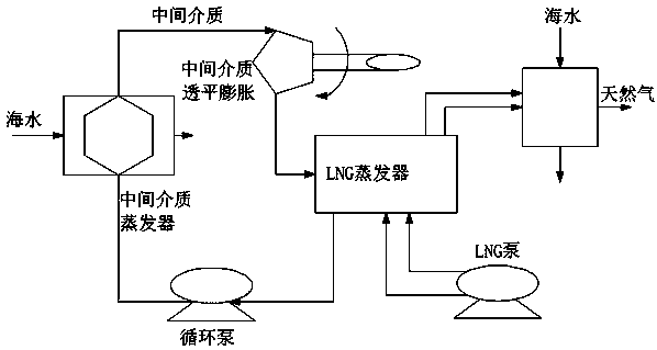
[0018] This embodiment discloses as figure 1 A cold energy recovery and utilization device for an LNG gasification station is shown, which is characterized in that the device includes an LNG evaporator and an intermediate medium evaporator, and the LNG evaporator circulates natural gas to the intermediate medium for evaporation through a circulation pump The intermediate medium evaporator attaches the cold energy in the natural gas to the intermediate medium through the intermediate medium, and the intermediate medium passes through the heat exchanger to process the natural gas into a high-pressure normal temperature gas and then transmits it to the intermediate medium turbine to expand and drive the engine generate electricity.

[0019] The LNG evaporator is connected to raw natural gas through an LNG pump, and the natural gas is separated from seawater through the LNG evaporator.

[0020] The intermediate medium turbine returns the natural gas extracted from the cold energy...

Embodiment 2

[0026] In this embodiment, the device in Example 1 is reused, and the cold energy of LNG is applied step by step. Shallow cooling is mainly used to build cold storage, medium cooling is mainly used to make ice, ice skating rinks and ski resorts, and deep cooling is mainly used Cryogenic grinding from air separation, etc. If you want to maximize the utilization rate of cold energy, you must use it in stages to maximize the application of energy.

[0027] In terms of efficient utilization of LNG cold energy, it is generally believed that the temperature difference power generation between the environment and LNG is the main way of utilization. If it is analyzed according to exergy economics, it can be known that only by using a large amount of electric energy can natural gas be liquefied, and in the liquefaction process, it is then completed by the cryogenic process (consuming about 8_50.OkW-h / t), however, Carnot’s theorem proposes that when a temperature difference of about 18...


PUM


Abstract

The invention relates to the technical field of energy use, in particular to a cold energy recycling device for an LNG gas station. The device comprises an LNG evaporator and an intermediate medium evaporator, the LNG evaporator circulates natural gas to the intermediate medium evaporator through a circular pump, the intermediate medium evaporator carries cold energy in the natural gas to intermediate media through the intermediate media, the intermediate media processes the natural gas to high-pressure normal-temperature gas through a heat exchanger to be conveyed to an intermediate medium turbine to drive an engine to generate power in an expansion manner, the recycling device is simple in structure, the LNG low-temperature cold energy characteristics are applied, working media (the intermediate media) are liquified, and then gasified, the media can do expansion work in a steam turbine, kinetic energy is generated, and is converted into electric energy through an electric generator,energy use is optimized, resources are saved, and the higher market application prospect is achieved.

Description

technical field [0001] The invention relates to the technical field of energy utilization, in particular to a cold energy recycling device for an LNG gasification station. Background technique [0002] Since 1980, LNG exports have grown at an annual rate of almost 8%. In 2000, the global LNG trade volume was 1.055 million tons, an increase of 11.2% over the previous year. According to statistics, the global LNG trade volume in 2010 exceeded 140 million tons and continued to grow. The world's natural gas consumption increases by an average of 500 billion cubic meters every 10 years. At present, the proportion of natural gas consumption in the world's energy consumption structure has reached 35%, and it has become the second largest energy source next to petroleum. Now liquefied natural gas (LNG) is liquefied natural gas (LNG), which is stored at a temperature of about 110K and a pressure of 0.1Mpa. The ingredient is methane. Since its volume is only 1 / 600 of the gaseous st...

Claims


Application Information

Patent Timeline
IPC IPC(8): F01K27/00F01K25/00F01K25/08F01K25/10F01K19/10F22B3/02
CPCF01K19/10F01K25/00F01K25/08F01K25/10F01K25/103F01K27/00F22B3/02
Inventor 汤云普赵媛媛
Owner 汤云普
Why Eureka
Try Eureka