
Metal detection device

A metal detection and transmitting coil technology, applied in measurement devices, geophysical measurement, radio wave measurement systems, etc., can solve the problems of large volume, offset of balance point, poor consistency control of detection effect, etc.

Inactive Publication Date: 2020-07-10
惠州市迈测科技有限公司
View PDF11 Cites 2 Cited by
  • Summary
  • Abstract
  • Description
  • Claims
  • Application Information

AI Technical Summary

Problems solved by technology

However, in the setting scheme of this kind of traditional metal detection device, the electrical parameters of the coil need to be strictly controlled when the transmitting coil is wound. The imbalance of the electrical parameters will cause no vibration or balance point shift, which will bring serious problems to the control of circuit parameters. A great disadvantage, resulting in poor consistency control of the detection effect, and the transmitting coil of this type of metal detection device needs to be wound on the core material, so the volume is large, and in principle it can only identify whether there is a metal object within the detection range , cannot identify its properties and location information, especially its magnetic properties and precise location information cannot be determined

Method used


Image

  • Metal detection device
  • Metal detection device
  • Metal detection device

Examples


Embodiment 1

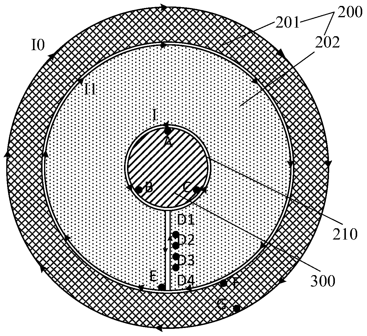
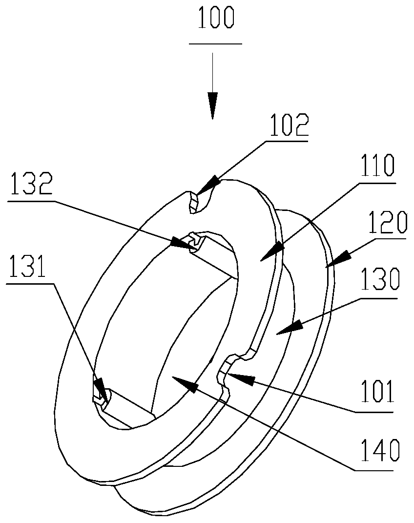
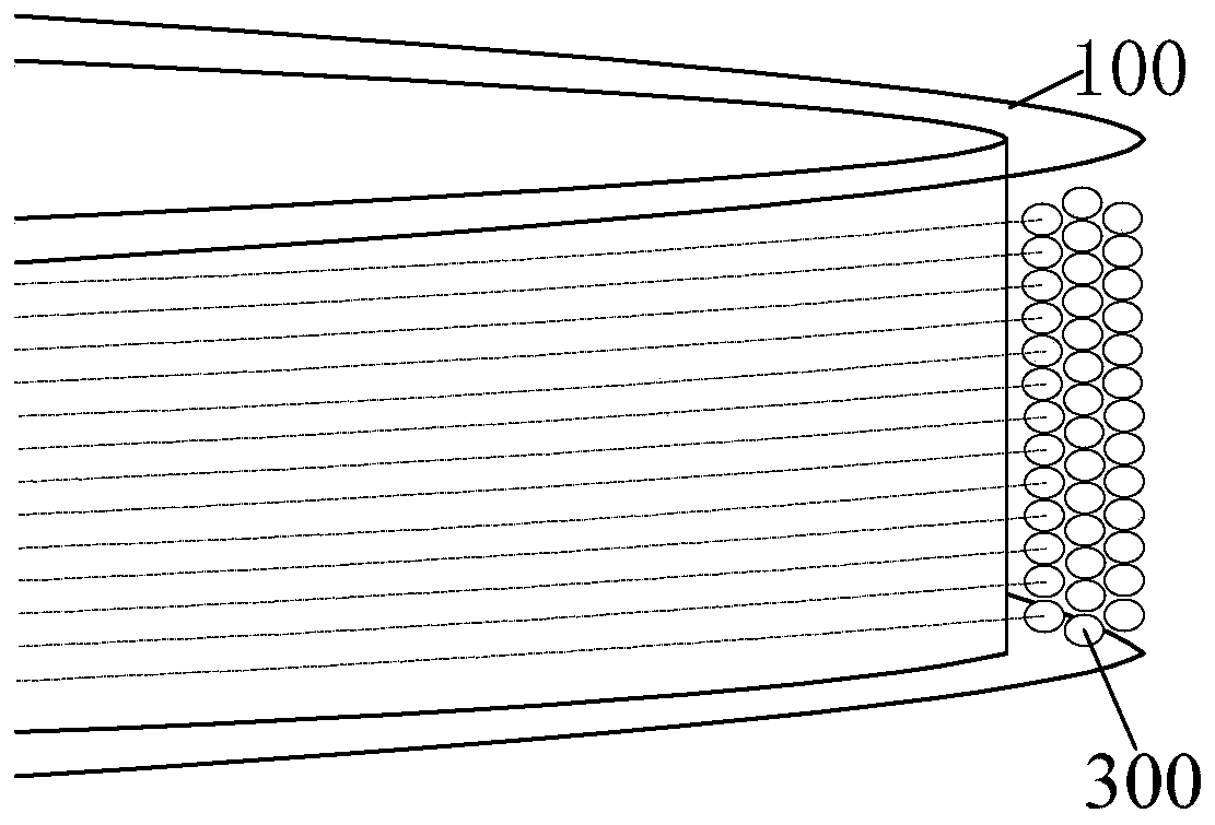
[0036] The metal detection device includes a receiving coil 200, a transmitting coil 300, a winding bobbin 100, a circuit board 20, a signal conditioning circuit 21 and a software module (not shown in the figure). The receiving coil 200 includes a main coil 201 and a secondary coil 202; and the transmitting coil 300, the secondary coil 202 and the primary coil 201 are arranged independently on the circuit board 20 according to a concentric structure from inside to outside, and the transmitting coil 300, the primary coil 201, the secondary coil The respective start ends and end ends of 202 are respectively electrically connected to corresponding components on the circuit board 20 .

[0037] The winding frame 100 is made of non-conductive material, such as plastic material, ferrite PVC material, phenol bakelite, ceramic lamp and other materials, preferably the winding frame 100 is made of PVC material with certain flexibility and low cost. The winding frame 100 is a columnar str...

Embodiment 2

[0060] The main difference between the metal detection device in this embodiment and Embodiment 1 is as follows:

[0061] like Figure 5A As shown, the secondary coil 202 adopts a group of coils to form a ring-shaped structure (the solid line in the figure), and the area formed by the ring is an open ring, that is, a metal copper wire is used to press between adjacent coils. Staggered open loops are continuously wound to form multi-turn coils and printed on the circuit board 20 . The metal copper wire includes a starting point E and an ending point D. The main coil 201 also adopts a circular ring structure (the dotted line in the figure) formed by a group of coils spirally surrounding multiple groups of coils, and the circular ring structure is a closed loop, which includes a starting point F and an ending point G point.

Embodiment 3

[0063] The main difference between the metal detection device in this embodiment and Embodiment 1 is as follows:

[0064] like Figure 5B As shown, the secondary coil 202 is divided into two closed-loop groups (2021, 2022), and each closed-loop group has a start end and an end end. The area formed by the two closed-loop groups (2021, 2022) is an open loop. The two closed-loop groups (2021, 2022) share a starting point E, the closed-loop group 2021 has an ending point D1, and the closed-loop group 2022 has an ending point D2. The overall structure formed by the inside of the two closed-loop groups (2021, 2022) is a circular ring, and the outside structure is a square ring structure and is an open ring; like this, the inside of the secondary coil 202 can be connected with the circle placed on the central circle 210. The shape and structure of the ring-shaped transmitting coil 300 are matched, and the outside can be matched with the shape and structure of the square-ring struct...


PUM

PropertyMeasurementUnit
Heightaaaaaaaaaa
Diameteraaaaaaaaaa

Abstract

The invention discloses a metal detection device. The metal detection device comprises a receiving coil, a transmitting coil and a circuit board, the receiving coil comprises a main coil and an auxiliary coil; the transmitting coil, the auxiliary coil and the main coil are independently distributed on a circuit board from inside to outside according to a concentric structure; the starting end andthe ending end of each of the transmitting coil, the main coil and the auxiliary coil are electrically connected with corresponding components on the circuit board respectively. In the device, an alternating magnetic field is formed through a transmitting signal of the transmitting coil; a target metal object is excited to generate an alternating vortex magnetic field; phase lag of vortex magneticfields generated by metal with different magnetic conductivities is different, the receiving antenna coil is induced by the vortex magnetic fields to generate induced electromotive force, the frequency of the induced electromotive force is the same as the frequency of transmitted signals, whether metal exists or not and the position of the metal are determined by judging the amplitude of the received signals, and then the magnetic property is determined by judging the phase.

Description

technical field [0001] The invention relates to the field of metal electromagnetic induction device preparation, in particular to a metal detection device. Background technique [0002] At present, traditional metal sensing devices are mainly used to detect the presence or absence of metal objects. Most of these metal sensing devices use a resonant transmitting coil with two windings and a feedback balance circuit. The primary winding of the transmitting coil is used as the transmitting antenna, and the secondary winding is used as the feedback path. When the circuit is working, the feedback circuit regulates and suppresses the self-excited oscillation, and the circuit is in a state of dynamic balance. When a metal object enters the range of the antenna transmitting signal, it is excited by the transmitting magnetic field to generate an eddy current inside it. The eddy current will consume energy and break the original balance point to establish a new dynamic balance. During...

Claims


Application Information

Patent Timeline
IPC IPC(8): G01V3/11
CPCG01V3/104
Inventor 敖敏郑以磊郭清春
Owner 惠州市迈测科技有限公司
Learn More