Al technical title is built by PatSnap Al team. It summarizes the technical point description of the patent document.
A transformer and functional technology, applied in the field of transformers with cooling function, can solve the problems affecting the normal operation of transformers, unfavorable permanent installation of transformers, loose installation of transformers, etc., and achieve the effects of stable work, reduced impact and increased stability
Active Publication Date: 2020-07-10
湖北金力特电气有限公司
View PDF8 Cites 1 Cited by
Summary
Abstract
Description
Claims
Application Information
AI Technical Summary
This helps you quickly interpret patents by identifying the three key elements:
Problems solved by technology
Method used
Benefits of technology
Problems solved by technology
[0002] Transformer is a device that uses the principle of electromagnetic induction to change AC voltage. The main components are primary coil, secondary coil and iron core (magnetic core). The main functions are: voltage conversion, current conversion, impedance conversion, isolation, voltage stabilization (magnetic Saturated transformers), etc., can be divided into: power transformers and special transformers (electric furnace transformers, rectifier transformers, power frequency test transformers, voltage regulators, mining transformers, audio transformers, intermediate frequency transformers, high frequency transformers, impact transformers, instrument Transformers, electronic transformers, reactors, transformers, etc.); However, during the working process of traditional outdoor transformers, the transformer is usually affected by the impact of rainwater, which makes the transformer shell corroded, and the transformer vibrates under the impact of rainwater, which affects the transformer. The normal work of the transformer, and the long-term rain wash makes the transformer loose, which is not conducive to the long-term installation of the transformer.
Method used
Image
Click on the blue label to locate the original text in one second.
Reading with bidirectional positioning of images and text.
Examples
Embodiment Construction
[0020] Attached below Figure 1-4 The specific implementation manner of the present invention will be described in further detail.
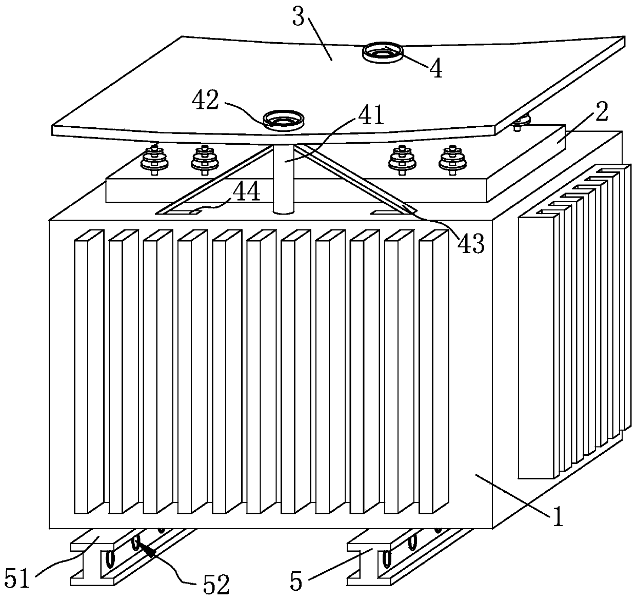
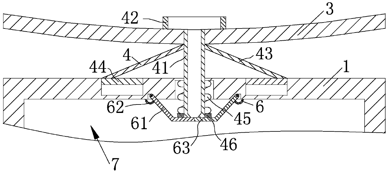
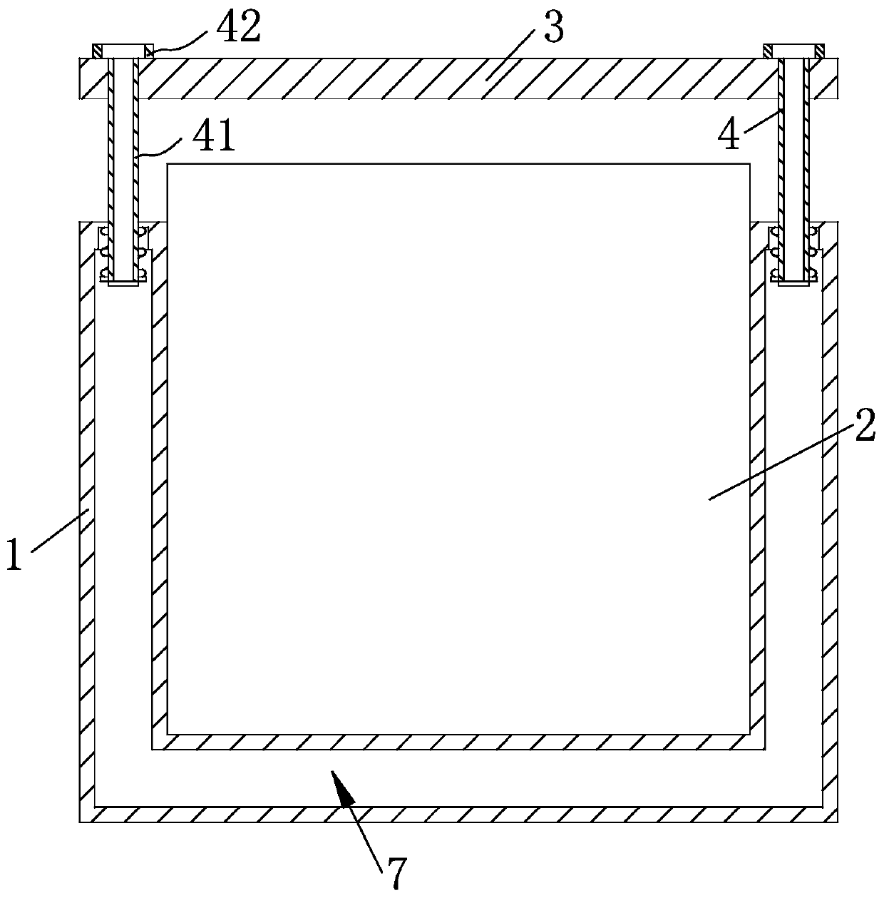
[0021] Depend on Figure 1-4 It is given that a transformer with a cooling function in the present invention includes a housing 1, a transformer body 2 is installed on the inner side wall of the housing 1, and the inner side wall of the housing 1 is provided with a cooling hole for the operation of the transformer body. A liquid storage chamber 7, the housing 1 is connected with an adjustment structure 4 for collecting rainwater for cooling, the adjustment structure 4 is connected with a protective cover 3 for the transformer body 2 to keep out the rain, and the housing 1 is connected with a The adjustment structure 4 is a switch and closed protection structure 6 , the protection structure 6 is connected to the adjustment structure 4 , and the housing 1 is connected to a mounting structure 5 for mounting and fixing the transformer body 2 .
[0...
PUM
Abstract
The invention discloses a transformer with a cooling function. The transformer comprises a shell, a transformer body is installed on the inner side wall of the shell. The inner side wall of the shellis provided with a liquid storage chamber used for cooling of the transformer body during work. The transformer body is shielded and protected through a protective cover at the top end of the transformer body; rainwater is separated and dredged; contact between the transformer body and rainwater is reduced; the transformer body is protected; in the process rain water impacts the protective cover,the protective cover slides towards the transformer body; when a fixed pipe slides down to enter the inner side wall of the shell, the spring extends to generate elastic force; and meanwhile, a supporting rod slides downwards to push a supporting block to slide into the inner side wall of the shell to reduce vibration of the protective cover, so that impact of rainwater on the transformer body inthe shell is reduced, stable work of the transformer body is facilitated, the loosening condition of the shell is prevented, the protective cover is supported through the supporting rod, and the stability of the protective cover is improved.
Description
technical field [0001] The invention relates to the technical field of transformers, in particular to a transformer with a cooling function. Background technique [0002] Transformer is a device that uses the principle of electromagnetic induction to change AC voltage. The main components are primary coil, secondary coil and iron core (magnetic core). The main functions are: voltage conversion, current conversion, impedance conversion, isolation, voltage stabilization (magnetic Saturated transformers), etc., can be divided into: power transformers and special transformers (electric furnace transformers, rectifier transformers, power frequency test transformers, voltage regulators, mining transformers, audio transformers, intermediate frequency transformers, high frequency transformers, impact transformers, instrument Transformers, electronic transformers, reactors, transformers, etc.); However, during the working process of traditional outdoor transformers, the transformer i...
Claims
Application Information
Patent Timeline
Application Date:The date an application was filed.
Publication Date:The date a patent or application was officially published.
First Publication Date:The earliest publication date of a patent with the same application number.
Issue Date:Publication date of the patent grant document.
PCT Entry Date:The Entry date of PCT National Phase.
Estimated Expiry Date:The statutory expiry date of a patent right according to the Patent Law, and it is the longest term of protection that the patent right can achieve without the termination of the patent right due to other reasons(Term extension factor has been taken into account ).
Invalid Date:Actual expiry date is based on effective date or publication date of legal transaction data of invalid patent.