Cosmetic mirror

A cosmetic mirror and mirror rod technology, applied in the field of cosmetic mirrors, can solve the problems of imperfect grip design, inability to adjust, short battery life, etc. Effect

Pending Publication Date: 2020-07-14
ORANGE VIEW LTD
View PDF6 Cites 3 Cited by
  • Summary
  • Abstract
  • Description
  • Claims
  • Application Information

AI Technical Summary

Problems solved by technology

[0002]Cosmetic mirrors are a kind of classification of mirrors. They are generally small in size and used on dressing tables. The common cosmetic mirrors on the market are round, square, etc. With the Its role is different from places, and its design is more functional, and with different application scenarios, more and more functional points are designed on it, such as use in dark environments, such as now with the development of live broadcast technology , makeup mirrors with supplementary light effect or capable of forming light are even more popular, and the existing cosmetic mirrors with supplementary light effect, due to the unsatisfactory setting of the light source structure, have poor light quality or uneven light, etc. problem, and the design of the handle is not ideal. When the handle is matched with the vanity mirror body, it is not very convenient to adjust the angle; at the same time, because only the power supply is set on the vanity mirror body, resulting in the vanity mirror body It is too bloated, and the base and the mirror rod are generally fixedly connected, so that the entire cosmetic mirror takes up too much storage space; due to structural design problems, the existing cosmetic mirror cannot be placed with a large-capacity battery, resulting in short battery life. Frequent charging is required; the infrared sensor of the makeup mirror can only sense a fixed distance, and the distance cannot be adjusted to achieve the habits of different users

Method used


Image

  • Cosmetic mirror
  • Cosmetic mirror
  • Cosmetic mirror

Examples


Embodiment 1

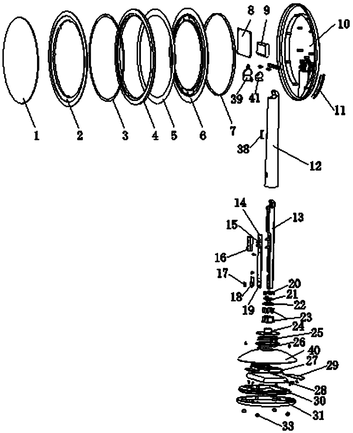
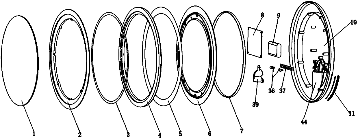
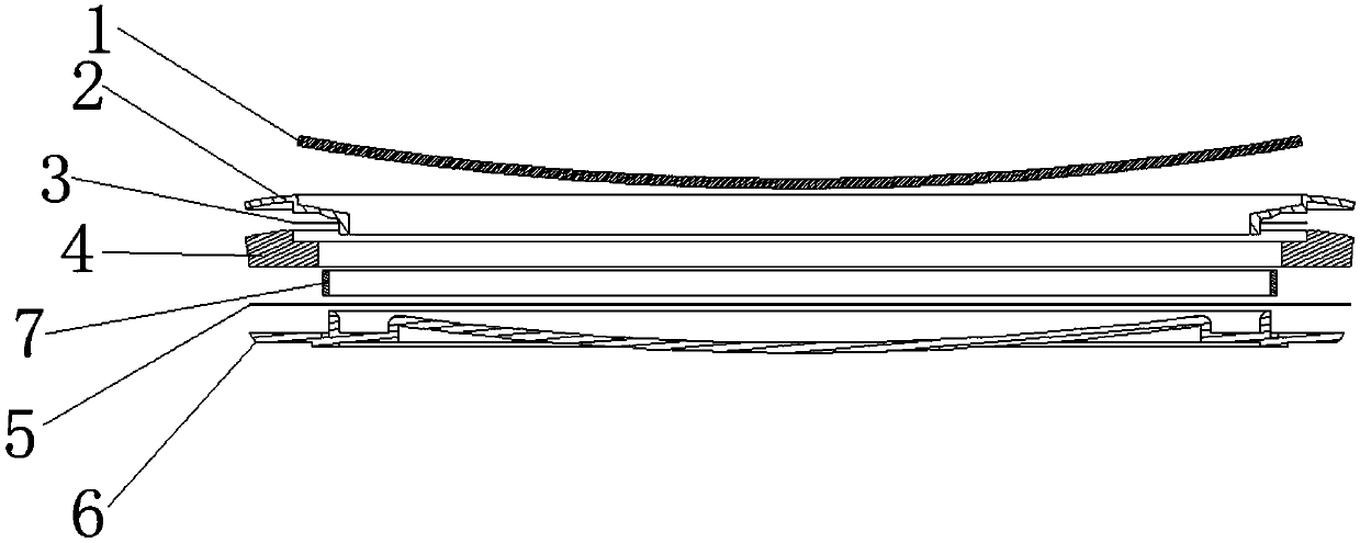
[0055] The present invention proposes a vanity mirror, which can solve the shortcomings of poor light source quality or uneven light in prior art vanity mirrors with light sources. It adopts a special light source mirror body structure design, combined with light source control. The circuit structure can realize the uniformity of light and effectively improve the quality of light. At the same time, after the set mirror rod is connected with the cosmetic mirror body, it can realize the multi-angle tilting operation of the cosmetic mirror body, so as to facilitate the user to observe from multiple angles, such as Figure 1~Figure 11 As shown, the following arrangement method is adopted in particular: including a vanity mirror body, a mirror rod 42 and a base 32 detachably connected with the mirror rod 42 for setting the main power supply system, the mirror rod 42 is provided with a mirror rod main body and a The adsorption structure matched with the main body of the mirror rod, t...

Embodiment 2

[0061] This embodiment is further optimized on the basis of the foregoing embodiments, and the same parts as the foregoing technical solutions will not be repeated here, such as Figure 1~Figure 11 As shown, further in order to better realize the present invention, the following arrangement structure is adopted in particular: the control system is provided with a control circuit board 8, a battery 9 and a controller 11 that adopts an infrared control mode or a touch control mode, and the battery 9 Installed between the control circuit board 8 and the back shell 10, the control circuit board 8 is installed between the mirror body and the battery 9, the controller 11 is installed on the side of the back shell 10 or on another side opposite to the vanity mirror body One side, and the controller 11 controls the power supply on and off between the mirror body, the control circuit board 8 and the battery 9 and the power supply of the mirror body.

[0062]As a preferred setting schem...

Embodiment 3

[0064] This embodiment is further optimized on the basis of the foregoing embodiments, and the same parts as the foregoing technical solutions will not be repeated here, such as Figure 1~Figure 11 As shown, further in order to better realize the present invention, the following arrangement structure is particularly adopted: when the controller 11 adopts the infrared control mode, it includes an infrared PCB board 45, a light-transmitting plate 46 and a light-shielding silica gel sheet 47 arranged in sequence, And the infrared PCB board 45 is arranged at the reserved hole on the back shell 10, an infrared emitter 48 and an infrared receiver 49 are also arranged on the infrared PCB board 45, and an infrared emitter is set on the transparent plate. and holes for the infrared receiver.

[0065] Preferably, the controller 11 adopts a control structure based on a touch control mode or an infrared control mode. When infrared control is adopted, the controller includes an infrared PC...


PUM


Abstract

The invention discloses a cosmetic mirror. The cosmetic mirror comprises a cosmetic mirror body, a mirror rod and a base detachably connected with the mirror rod and used for arranging a main power supply system. A mirror rod main body and an adsorption structure matched with the mirror rod main body are arranged on the mirror rod, the adsorption structure comprises an electrode circuit board usedfor arranging a grounding pointer, at least two power supply pointers and at least two data pin pointers, and a conductive coil matched with the grounding pointer, the power supply pointers and the data pin pointers is arranged on the base; the cosmetic mirror body comprises a back shell, a mirror body and a control system based on an infrared control mode or a touch control mode. The mirror bodyand the control system are both installed on the back shell. A back groove is further formed in the side, opposite to the side where the mirror body is installed, of the back shell, the mirror rod isinstalled in the back groove in a matched mode through a hinge, multi-angle pitching operation can be achieved between the mirror rod and the cosmetic mirror body through the hinge, use is convenientfor a user, the base and the mirror rod are designed through a detachable connecting structure, and storage is convenient for the user.

Description

technical field [0001] The invention relates to the field of vanity mirror technology and the like, in particular to a vanity mirror. Background technique [0002] Vanity mirror is a classification of mirrors. It is generally small in size and used on a dressing table. The common vanity mirrors on the market are round, square, etc. With their functions and different places, their designs are more functional. With the different application scenarios, there are more and more functional points designed on it, for example, it can be used in dark environments. It is very popular, but the existing cosmetic mirrors with supplementary light effect have problems such as poor light quality or uneven light due to the unsatisfactory setting of the light source structure, and the design of the holding part is not ideal. After the handle is matched with the cosmetic mirror body, it is not very convenient to adjust the angle; at the same time, because the power supply is only installed on...

Claims


Application Information

Patent Timeline
IPC IPC(8): A45D42/10F21V33/00F21V19/00F21V29/10H02J9/06F21Y115/10
CPCA45D42/10F21V33/0012F21V19/001F21V29/10H02J9/061F21Y2115/10
Inventor 陈亮
Owner ORANGE VIEW LTD
Why Eureka
Try Eureka