Gas leaking valve and sphygmomanometer
A leak valve and gas technology, applied in vascular assessment, cardiac catheterization, etc., can solve the problems of large difference in leak rate, easy to be affected by the environment, and unable to leak normally, so as to reduce the possibility and impact Effect
- Summary
- Abstract
- Description
- Claims
- Application Information
AI Technical Summary
Problems solved by technology
Method used
Image

Examples
no. 1 example
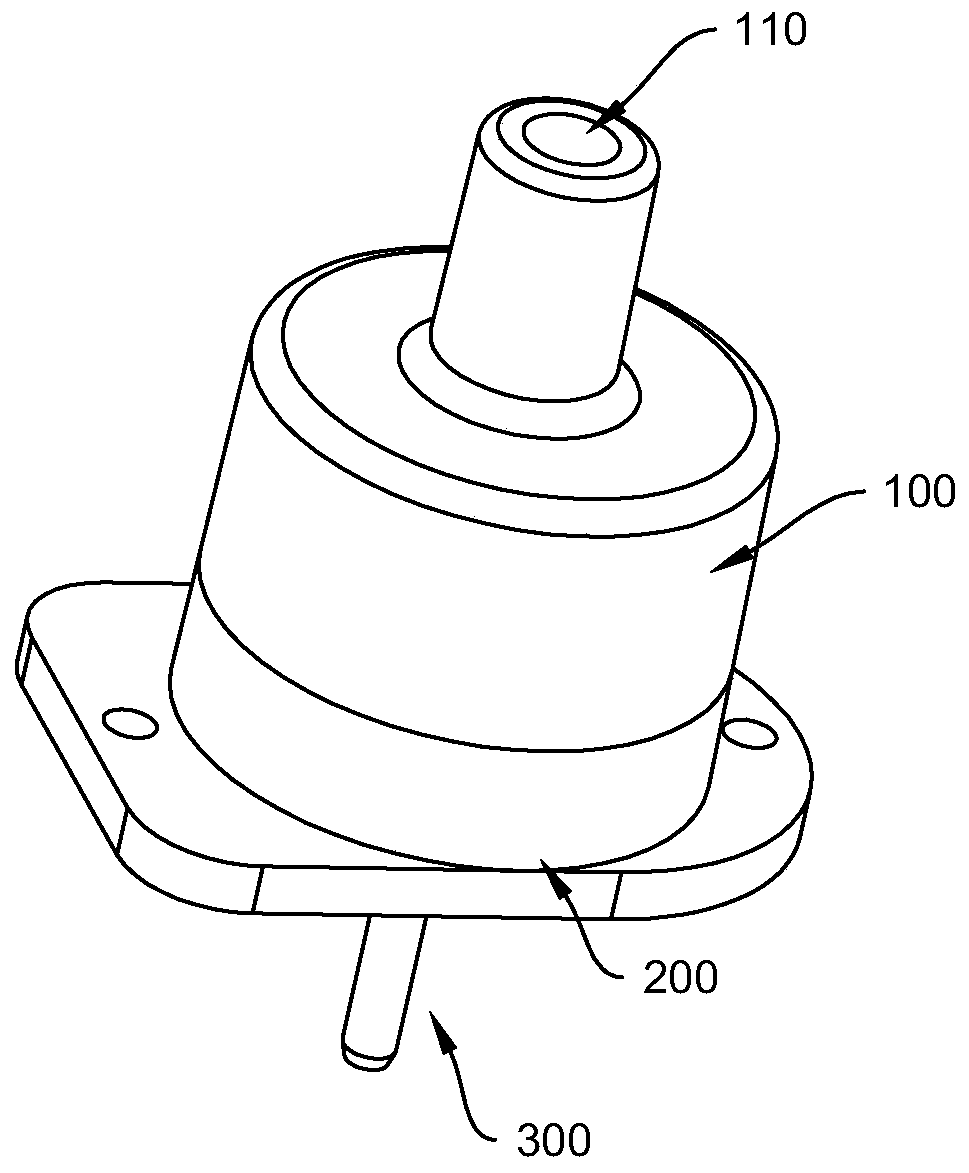
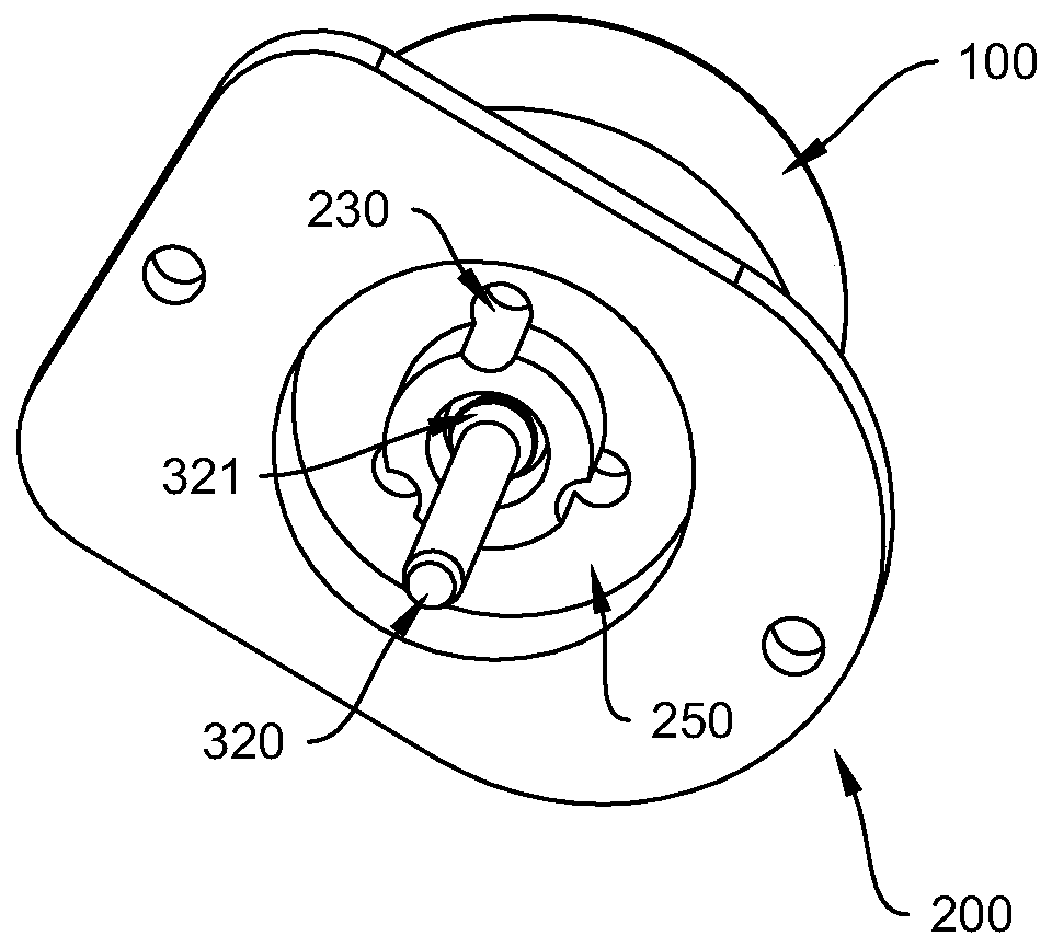
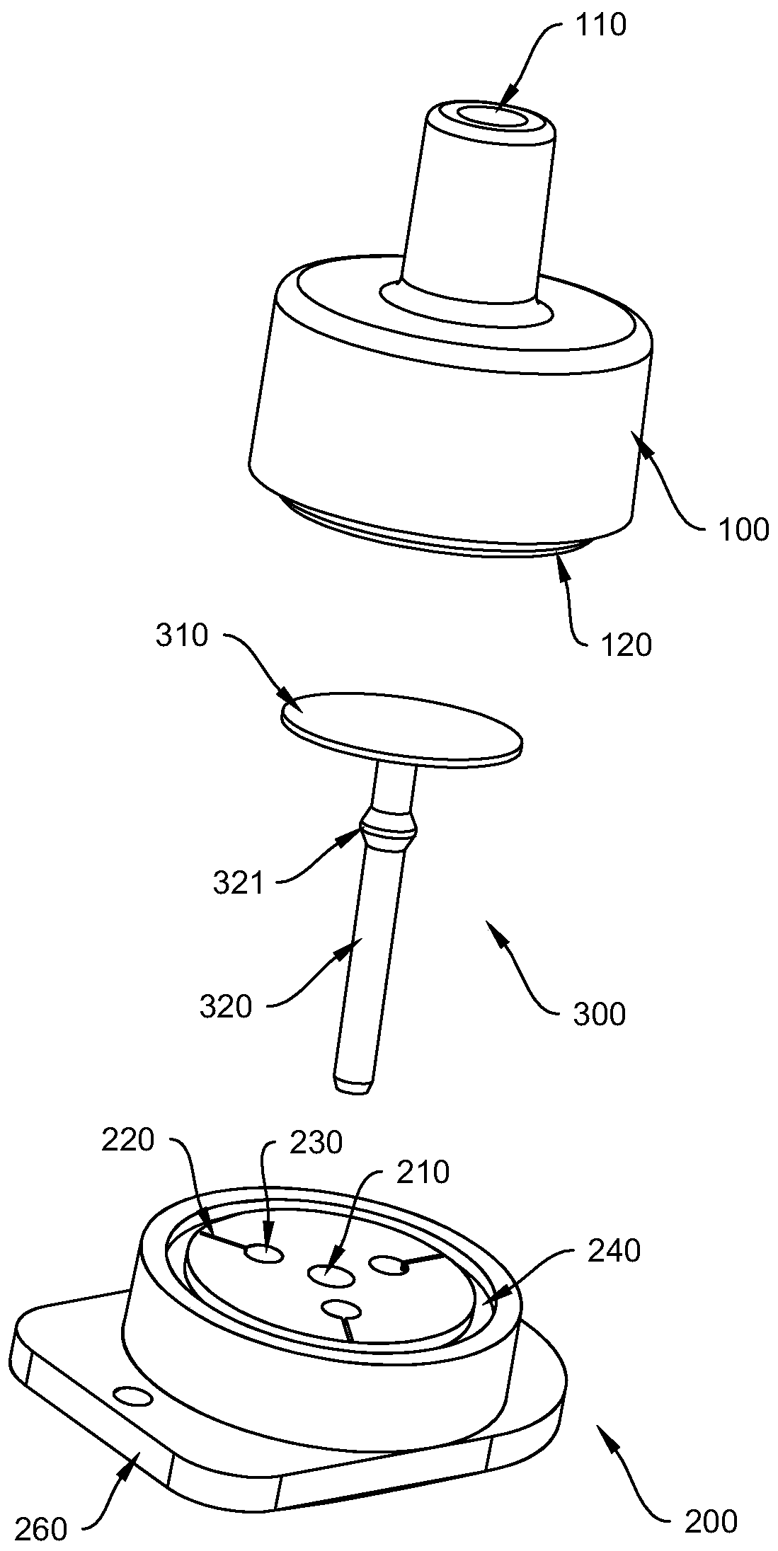
[0035] refer to Figure 1 to Figure 2 , the leakage valve in this embodiment includes an upper cover 100 , a lower cover 200 and a middle piece 300 . The upper cover 100 is located on top of the lower cover 200 . refer to image 3 and Figure 4 , the cavity between the upper cover 100 and the lower cover 200 forms the air storage portion 400 , and the top of the middle piece 300 is located in the air storage portion 400 . Both the upper cover 100 and the lower cover 200 are plastic parts, and the middle part 300 is a silicone part. The upper cover 100 is fixedly connected with the lower cover 200 . Specifically, it may be fixed by means of bonding or the like. Preferably, the bottom of the upper cover 100 protrudes downwards with a clamping block 120, and the top of the lower cover 200 is provided with a clamping groove 240. When the upper cover 100 and the lower cover 200 are assembled, the clamping block 120 is clamped into the clamping groove 240 for limit.
[0036] ...
no. 2 example
[0046] This embodiment is an alternative embodiment of the first embodiment, refer to Figure 5 , in this embodiment, the end of the groove 220a (air outlet channel) is not aligned with the air outlet 230a, and the two are staggered. At this time, the bottom surface of the covering part must protrude upwards, and cannot be set as a plane, so that there is an accommodation space between the bottom surface of the covering part and the top surface of the lower cover 200a. The gas flows into the accommodation space between the bottom surface of the cover part and the top surface of the lower cover 200a from the groove 220a (gas outlet channel), and then flows into the gas outlet 230a. In this embodiment, the gas can undergo secondary buffering in the accommodation space between the bottom surface of the cover part and the top surface of the lower cover 200a, so that the gas can flow into the gas outlet 230a more smoothly. Moreover, during manufacture, there is no need to intentio...
no. 3 example
[0048] This embodiment is an alternative embodiment of the first embodiment, refer to Image 6 , in this embodiment, the groove on the lower cover 200b is replaced with a protrusion 220b, and the protrusion 220b will prop up the cover part upwards, so that the positions on both sides of the protrusion 220b on the top surface of the lower cover 200b are in line with the A gap is formed between the bottom surfaces of the covering parts, and the gap is the gas outlet channel, and the gas in the gas storage part 400 flows into the gas outlet 230b from the gap. In both the first embodiment and the second embodiment, it is necessary to process the groove on the lower cover after the injection molding is completed, which requires two processes to complete. In this embodiment, the grooves are changed into protrusions, and the protrusions can be made together when the lower cover 220b is injected, which reduces one process and improves the efficiency.
PUM
 Abstract
Description
Claims
Application Information
 - R&D
- Intellectual Property
- Life Sciences
- Materials
- Tech Scout
- Unparalleled Data Quality
- Higher Quality Content
- 60% Fewer Hallucinations
Browse by: Latest US Patents, China's latest patents, Technical Efficacy Thesaurus, Application Domain, Technology Topic, Popular Technical Reports.
© 2025 PatSnap. All rights reserved.Legal|Privacy policy|Modern Slavery Act Transparency Statement|Sitemap|About US| Contact US: help@patsnap.com