
An automatic hitting acupuncture point massager

A massager and acupoint technology, which is applied in the direction of vibration massage, massage auxiliary products, equipment for compressing reflex points, etc., can solve the problems of tired hands, small massage force, heavy weight, etc., and achieve accurate hitting position Great strength and good massage effect

Active Publication Date: 2022-03-25
广东淼潮科技有限公司
View PDF0 Cites 0 Cited by
  • Summary
  • Abstract
  • Description
  • Claims
  • Application Information

AI Technical Summary

Problems solved by technology

However, due to the need for power supply, the electric massager is inconvenient to use when there is a power outage or when going out, and because of the built-in motor, it is generally heavy and the hand is tired; the non-electric massager cannot automatically hit the acupuncture points of the human body during actual use. , and many users feel that the massage heads of non-electric massagers have the disadvantages of low massage force and difficulty in fully stimulating many acupoints on the human body, which cannot achieve a good massage effect

Method used

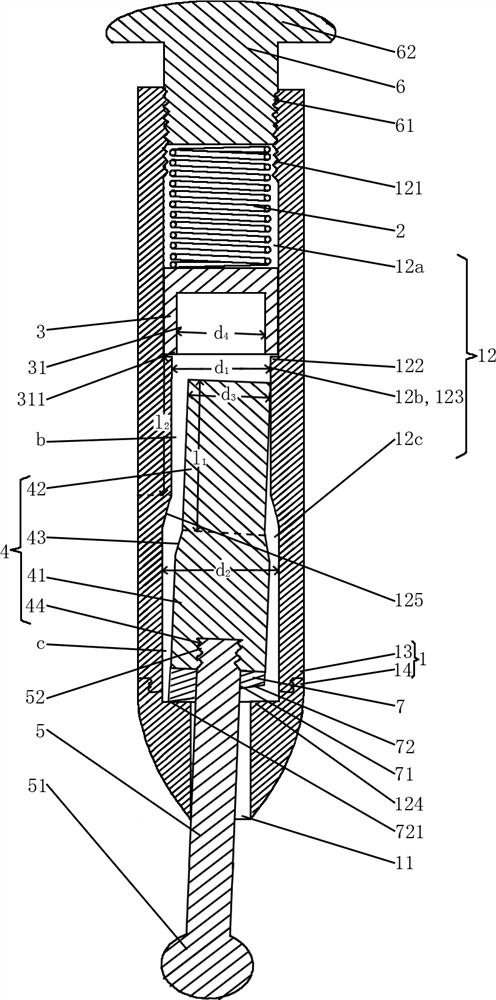
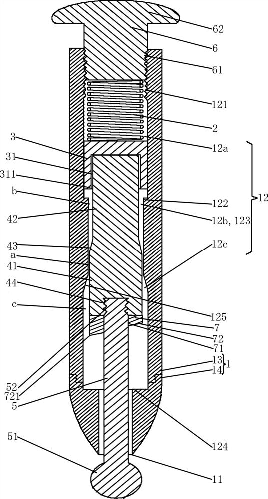

Image

  • An automatic hitting acupuncture point massager
  • An automatic hitting acupuncture point massager
  • An automatic hitting acupuncture point massager

Examples


Embodiment 1

[0025] like Figure 1-2 As shown, the automatic hitting acupoint massager in this embodiment includes a cylindrical shell 1, a return spring 2, a pressure head 3, a tube positive rod 4 and a massage rod 5, and the top of the cylindrical shell 1 is provided with a screw end cover 6, The bottom of the cylindrical shell 1 is provided with an outlet 11, and the cylindrical shell 1 is provided with a channel 12 perpendicular to the bottom surface of the screw end cap 6, and the channel 12 communicates with the outlet 11; the outer circumference of the lower half of the screw end cap 6 is provided with an external thread 61 , the inner side wall of the upper section of the channel 12 is provided with an inner thread 121 that matches the outer thread 61, and the screw end cap 6 is threadedly connected to the upper section of the channel 12; There is a tube positive channel section 123, the lower section of the channel 12 is provided with a second annular step 124, and the second annu...

Embodiment 2

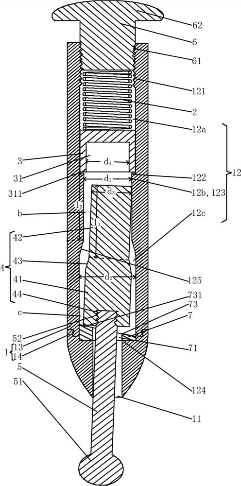
[0037] like Figure 3-4 As shown, the difference between the automatic hitting acupoint massager in this embodiment and Embodiment 1 is:

[0038] The bottom of the deflection ring 7 is fixedly connected with the second annular step 124 , the top of the deflection ring 7 is provided with a second inclined surface 73 inclined downward, and the higher part 731 of the second inclined surface 73 is in contact with the bottom of the pipe positive rod 4 . With this arrangement, the higher part 731 of the downwardly inclined second inclined surface 73 is in contact with the bottom of the pipe positive rod 4, and one end point of the top of the pipe positive rod 4 is in contact with the inner side wall of the channel 12, so that the pipe positive rod 4 leans against the on the inner wall of the channel.


PUM


Abstract

The invention discloses an automatic acupuncture point massager, which comprises a cylindrical casing, a return spring, a pressure head, a tube positive rod and a massage rod. The top of the cylindrical casing is provided with a screw end cover, and the bottom of the cylindrical casing is provided with an outlet. A channel perpendicular to the bottom surface of the screw end cover is provided in the shell, and the channel is connected with the outlet; the screw end cover is threadedly connected with the upper section of the channel; There is a second annular step in the lower section of the bottom, and the second annular step is above the outlet; the return spring, pressure head, and tube positive rod are in the channel from top to bottom; The offset ring that makes the tube positive rod eccentric, and the massage rod is in the offset ring and the outlet from top to bottom. The massager can automatically hit the acupuncture points of the human body, the hitting position is accurate, the hitting force is large and the force can be adjusted, has good massage effect, is easy to use, and is easy to carry.

Description

technical field [0001] The invention relates to a massager, in particular to an automatic hitting acupoint massager. Background technique [0002] With the gradual improvement of living standards, people's health awareness has become stronger and stronger, and various methods have been adopted to protect their health. There are many acupoints on the surface of the human body, which can be stimulated by massage, massage, acupuncture and other methods to clear the meridians, maintain health and treat diseases. Among them, there are many types of massage, including kneading massage, rubbing massage, vibration massage, etc., especially tapping vibration massage is more convenient. It uses the shape and hardness of the hammer to directly hit the relevant body positions or acupoints of the human body. , to relax tendons, activate blood circulation, relieve pain and relieve fatigue, and relieve fatigue. Existing percussion vibrating massagers generally include electric massagers ...

Claims


Application Information

Patent Timeline
Patent Type & Authority Patents(China)
IPC IPC(8): A61H39/04A61H23/00
CPCA61H39/04A61H23/004A61H2201/0153
Inventor 王立华彭燕芳王锐王臻林一灿王婷婷
Owner 广东淼潮科技有限公司
Learn More