Injection mold capable of finely adjusting glue feeding speed at pouring gates and using method
An injection mold and gate technology, which is applied in the field of injection molds that can fine-tune the glue feeding speed at the gate, can solve the problems of snake pattern or silver wire easily appearing at the gate, and achieve easy operation, avoidance of defects, and convenient use. Effect
- Summary
- Abstract
- Description
- Claims
- Application Information
AI Technical Summary
Problems solved by technology
Method used
Image

Examples
Embodiment 1
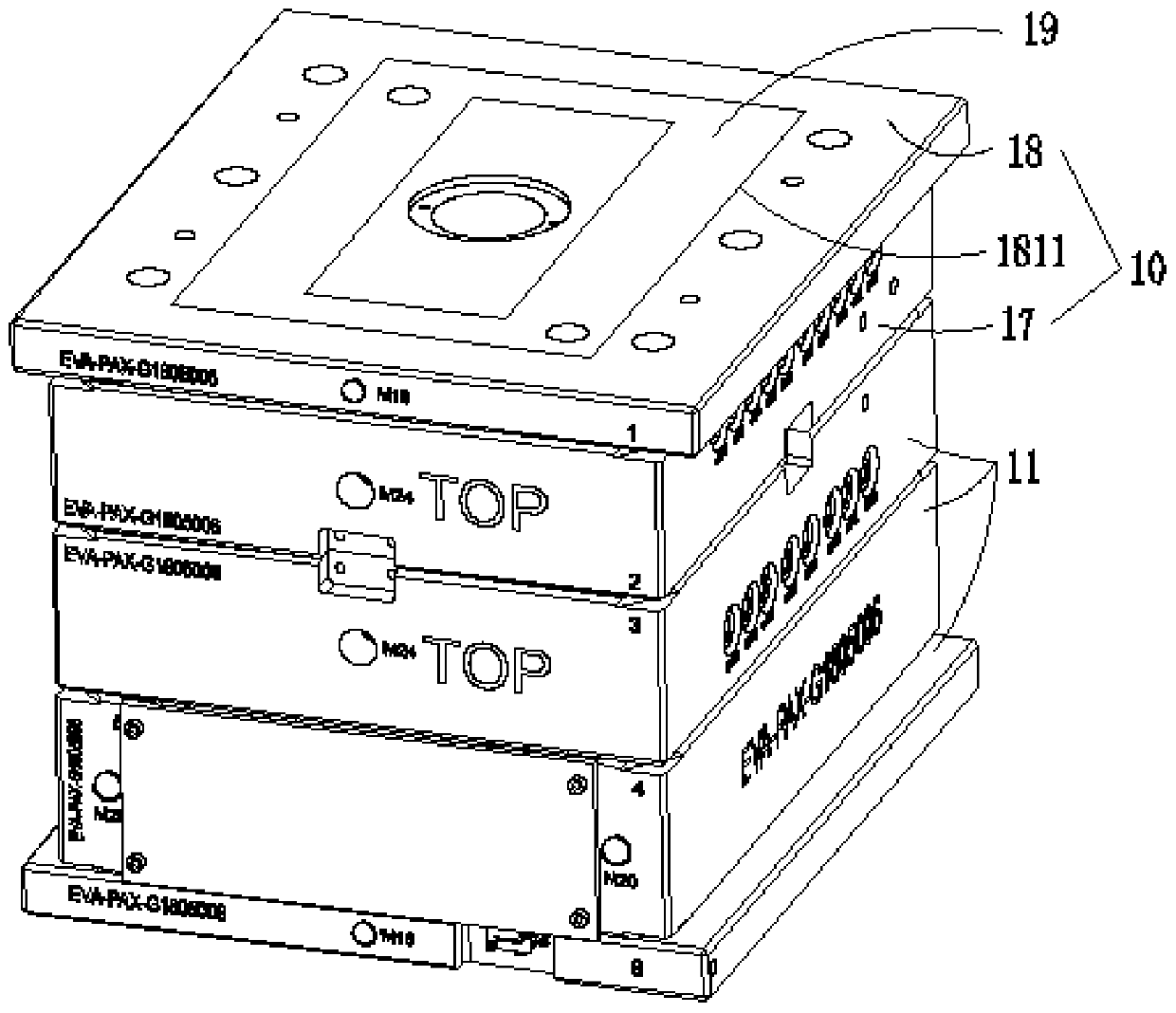
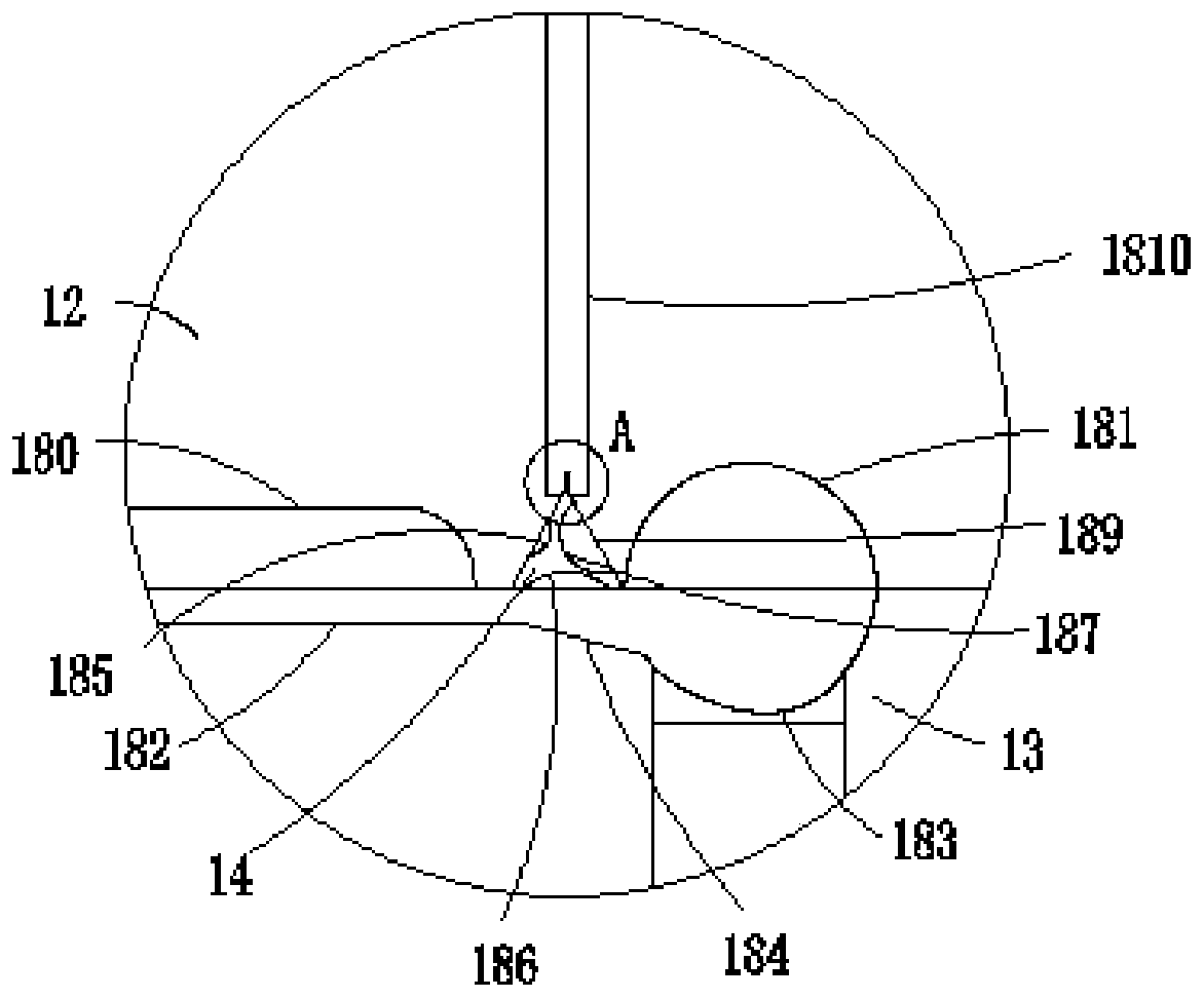
[0029] The embodiment of the present invention provides an injection mold that can finely adjust the glue feeding speed at the gate, such as Figure 1-Figure 6 As shown, it includes a front mold 10 and a back mold 11; the front mold 10 includes a front mold kernel 12; the back mold 11 includes a rear mold kernel 13 corresponding to the front mold kernel 12; the front mold kernel 12 is provided with a plurality of first cavities 180, and a plurality of groups of first sub-runners 181 corresponding to a plurality of first mold cavities 180; the first sub-runners 181 are not communicated with the first cavity 180; Multiple second cavities 182 corresponding to one cavity 180, multiple second runners 183 corresponding to multiple sets of first runners 181, and multiple sets of second runners 183 one-to-one Corresponding multiple gates 184; the gates 184 communicate with the second cavity 182 and the second runner 183;
[0030] The front mold 10 also includes a plurality of buffer ...
Embodiment 2
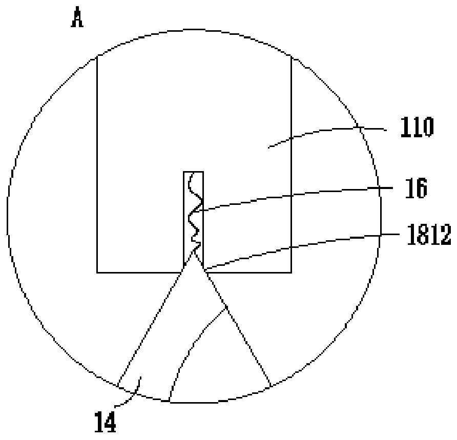
[0039] The embodiment of the present invention provides an injection mold that can finely adjust the glue feeding speed at the gate. Figure 7 As shown, the receiving slot 188 includes a first sub-slot 1813 located in the middle of the buffer iron block 14, and three groups of second sub-slots 1814 that are evenly distributed around the first sub-slot 1813; the first sub-slot 1813 is circular; The second sub-groove 1814 is a rectangular groove, and communicates with the side walls of the first sub-groove 1813 and the side of the buffer iron block 14; To ensure the accommodation space, after the buffer slot is selected, the fishing rope 16 is re-pressed into the second sub-slot 1814, and the buffer iron block 14 can be smoothly pushed back in the first installation slot 189.
[0040] Such as Figure 7 As shown, the bottom of the first sub-groove 1813 is threadedly connected with the first bolt 111 for winding the fishing rope 16; the first bolt 111 and the buffer iron block 14...
Embodiment 3
[0042] Embodiments of the present invention provide a method for using an injection mold, the method comprising the following steps:
[0043] Step S1: Fix one end of the fishing rope to the electromagnet, and then fix the electromagnet and the front mold core together.
[0044] Step S2: Fix the other end of the fishing rope to the buffer iron block, and turn the buffer iron block to select a designated buffer slot.
[0045] Step S3: After the buffer slot is selected, the buffer iron block is pushed into the first installation slot, the electromagnet is energized, and the buffer iron block is adsorbed, and injection molding production can be carried out.
[0046] Wherein, step S2 includes:
[0047] Step S20: Screw the first bolt into the first sub-slot first, and then wind the fishing rope onto the first bolt.
[0048] Step S21: After the winding is completed, the first bolt is tightened, and the first bolt cooperates with the buffer iron block to clamp the fishing rope, thus...
PUM
 Abstract
Description
Claims
Application Information
 - R&D
- Intellectual Property
- Life Sciences
- Materials
- Tech Scout
- Unparalleled Data Quality
- Higher Quality Content
- 60% Fewer Hallucinations
Browse by: Latest US Patents, China's latest patents, Technical Efficacy Thesaurus, Application Domain, Technology Topic, Popular Technical Reports.
© 2025 PatSnap. All rights reserved.Legal|Privacy policy|Modern Slavery Act Transparency Statement|Sitemap|About US| Contact US: help@patsnap.com