
Strapping machine and using method thereof

A technology for binding machines and binding ropes, which is applied in the field of binding machines for binding into small bundles, and can solve the problems of low efficiency, high cost, poor binding load-bearing capacity, etc.

Pending Publication Date: 2020-07-14
深圳市农科创网络有限公司
View PDF1 Cites 5 Cited by
  • Summary
  • Abstract
  • Description
  • Claims
  • Application Information

AI Technical Summary

Problems solved by technology

[0004] However, although the efficiency of the bundling method of the common bundling machine has been improved, it is actually caused by the inherent defect of using straps to bind the straps, which actually makes the straps form a loose ring that is sleeved on the object to be bundled. It cannot be tied tightly, and the binding has poor load-bearing capacity and is easy to break
[0005] And, in the process of harvesting vegetables to market sales, it is necessary to bundle strip vegetables into small bundles for storage, transportation and sales, or when bundling non-food strips in daily life and production. Most of the methods are tied by manual tying or tape binding. On the one hand, the workload is heavy, the efficiency is low, the cost is high, and the binding is not standardized, the feeling is rough, and the degree of standardization is low. It is easy to cause harmful residues such as adhesives. The traditional strapping machine cannot solve the above problems because of its inherent defects that cannot be tied tightly.

Method used

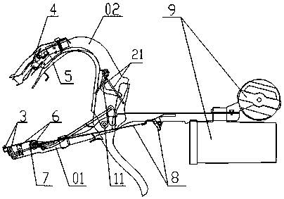
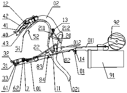

Image

  • Strapping machine and using method thereof
  • Strapping machine and using method thereof
  • Strapping machine and using method thereof

Examples


Embodiment Construction

[0022] In order to make the purpose, technical solution and advantages of the present invention clearer, the implementation manners of the present invention will be further described in detail below. However, the strapping machine provided by the present invention can be implemented in many different forms and is not limited to the embodiments described herein. On the contrary, the purpose of providing the embodiments is to make the disclosure of the strapping machine and the strapping method thereof more thorough and comprehensive.

[0023] Refer to attached figure 1 , 2 One embodiment of the present invention will be described. Also, for ease of understanding, the figure 1 , 2 The upper direction (upper side) and lower direction (lower side) and the left direction (left side) and right direction (right side) in the direction (left side) and right direction or back direction (right side).

[0024] Such as figure 1 As shown, the strapping machine provided by an embod...


PUM

PropertyMeasurementUnit
Diameteraaaaaaaaaa
Thicknessaaaaaaaaaa
Widthaaaaaaaaaa

Abstract

The invention discloses a strapping machine and a strapping method thereof, and particularly relates to a strapping machine for strapping strip-shaped objects together or strapping the strip-shaped objects into small bundles. The strapping machine comprises a base frame, a main arm, a rope releasing part, a rope holding part, a rope binding part, a supporting part, a hooping part and a conveying part, a strapping rope is wound on a strapped object, and meanwhile, a hooping material is used for hooping the combination part of the strapping rope wound on the strapped object to form a closed ropeloop so as to realize strapping of the strapped object. Traditional manual bundling is replaced, the bundling process of strip-shaped objects in daily production and life is semi-automatic, and onlyabout one second is needed for completing bundling; bundling is standard, the standardization degree is high, rapidness, attractiveness, safety and practicability are achieved, the production cost iseffectively reduced, and the device is particularly suitable for agricultural production and used for fixing branches and tendrils of crop plants such as tomatoes, cucumbers and grapes; and in addition, the strapping machine can be applied to strapping and binding requirements required in various links of production, transportation, storage, sales and the like of strip-shaped vegetables and otherfoods and strip-shaped non-foods.

Description

technical field [0001] The present invention relates to a binding machine and its binding method which can be applied in multiple links such as agricultural production, storage, sales and daily life production, especially a binding machine for binding strip-shaped objects together or into small bundles and its binding method. Background technique [0002] When planting tomatoes, cucumbers, beans, peppers, grapes, kiwis and other crops, we usually need to fix the vines or branches of the plants to guide their growth or assist them in fruiting, so as to improve crop yield and quality. The traditional solution is to manually use ropes or cloth strips to fix them by tying knots one by one. The more advanced method is to use tools such as a tying machine to tie the branches of the plants. [0003] For example, the invention patent with application publication number CN103025148A discloses a horticultural tying machine, which relates to horticultural tying machine technology for ...

Claims


Application Information

Patent Timeline
IPC IPC(8): B65B13/18B65B61/06A01G9/12A01G17/08
CPCA01G9/12A01G17/08B65B13/18B65B61/06
Inventor 刘永喻勋黄容
Owner 深圳市农科创网络有限公司
Learn More