Biomass gasifier control method

A control method and gasifier technology, applied in the manufacture of combustible gas, petroleum industry, etc., can solve the problems of low calorific value, harsh working environment, unstable gas production, etc., and achieve strong robustness and improved gas production quality Effect

Active Publication Date: 2020-07-14
BEIJING UNIV OF TECH
View PDF9 Cites 0 Cited by
  • Summary
  • Abstract
  • Description
  • Claims
  • Application Information

AI Technical Summary

Benefits of technology

This technology improves the stability and efficiency of an airborne pyrolysis process by controlling temperatures accurately during startup or after shutdowns. Additionally, this technology helps analyze the calorie values produced from different types of materials used on board at various stages throughout its life cycle.

Problems solved by technology

This patented technical problem addressed by this patents relates to improving the quality and quantity of fuel produced from biological sources like plants or animals without causing negative effects on their ecosystem. Current methods require significant effort for maintenance and adjustment over time due to changes caused during operation that affect both the yield and purity levels of these products.

Method used


Image

  • Biomass gasifier control method
  • Biomass gasifier control method

Examples


Embodiment Construction

[0012] The present invention will be further described below in conjunction with the accompanying drawings.

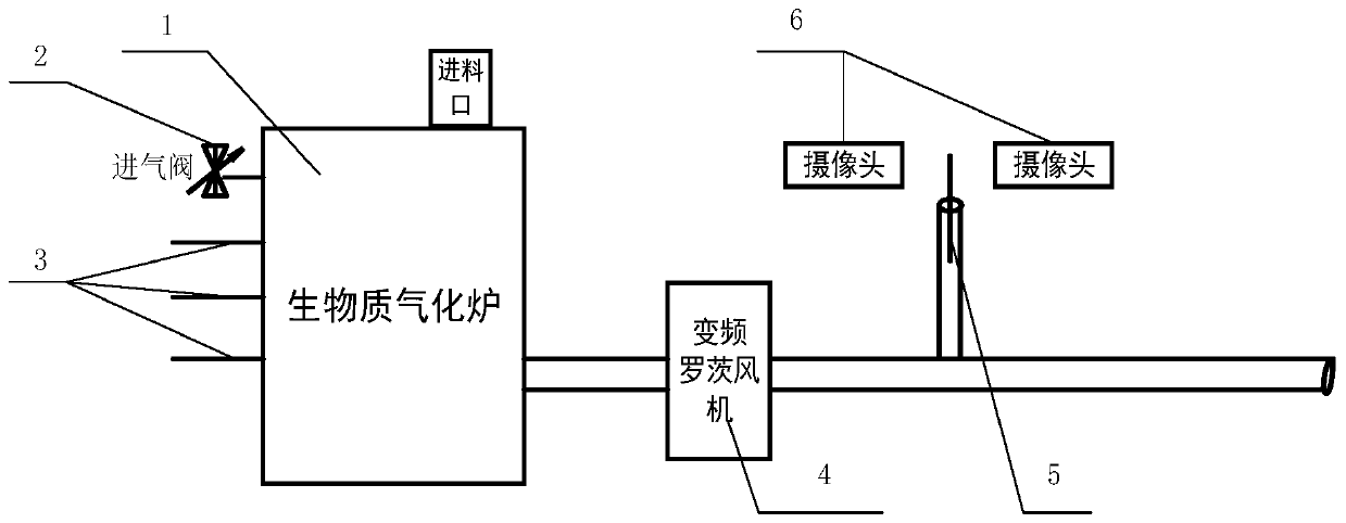
[0013] As shown in the figure, the biomass raw material enters the gasification furnace 1 through the feed port, and contacts with the gasification agent introduced into the furnace through the inlet valve 2. In the gasification furnace, it undergoes complex physical and chemical reactions to generate gas containing carbon monoxide and hydrogen. , methane and other combustible gases and nitrogen, carbon dioxide mixed gas, the mixed gas produced by the frequency conversion Roots blower 4 is extracted from the bottom of the gasifier, after the purification system, most of the mixed gas enters the subsequent gas storage device or other links through the pipeline, less Part of it is burnt at an open flame for the detection of gas calorific value.

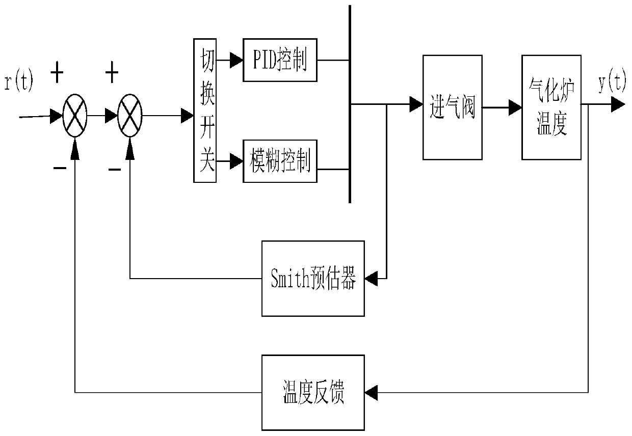
[0014] When controlling the temperature in the furnace, multiple sensors 3 around the furnace transmit the temperature to the ...


PUM


Abstract

The invention discloses a biomass gasifier control method and relates to the field of automatic control. The device of the application mainly comprises: a downdraft biomass gasification furnace, a gasification agent inlet valve, a plurality of temperature sensors arranged around the hearth, a roots blower, a temperature sensor at ever-burning fire and a data acquisition camera. The main emphasis is on that: the camera and the temperature sensors are combined to be applied to detection of calorific value information of gas-producing combustible gas, a calorific value coefficient concept is introduced, and during temperature loop control, a fuzzy-PID composite controller with Smith estimation is adopted to enable the temperature in the downdraft gasifier to be in the optimal gasification state.

Description


Claims


Application Information

Patent Timeline
Owner BEIJING UNIV OF TECH
Why Eureka
Try Eureka