Latch bolt mechanism and door lock with same

A technology of oblique tongue and lock case, which is applied in the field of mechanical locks, can solve the problems of troublesome opening of the door, easy entry of impurities into the hollow opening, troublesome installation of the lock case cover, etc., and achieves the effect of simple structural connection, simple structure and compact linkage

Pending Publication Date: 2020-07-14
WONLY SECURITY & PROTECTION TECH CO LTD
View PDF1 Cites 3 Cited by
  • Summary
  • Abstract
  • Description
  • Claims
  • Application Information

AI Technical Summary

Problems solved by technology

[0005] The technical problem to be solved by the present invention is to overcome the existing door lock latch mechanism in the prior art that needs to be opened by twisting the door handle, which is troublesome to use when opening the door, and in order to be suitable for installation, either a hollow opening is provided to easily enter impurities, or the lock needs to be opened The problem of troublesome installation of the shell cover

Method used


Image

  • Latch bolt mechanism and door lock with same
  • Latch bolt mechanism and door lock with same
  • Latch bolt mechanism and door lock with same

Examples


Embodiment 1

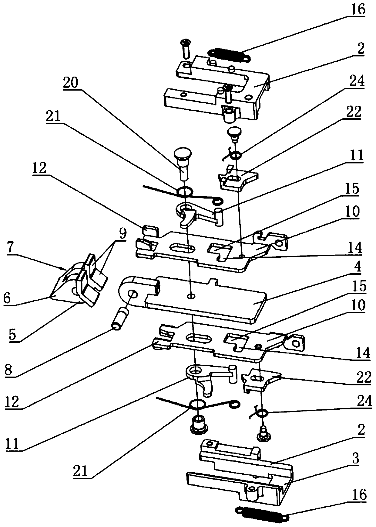
[0069] see Figure 1 to Figure 6 The bolt mechanism of the illustrated embodiment comprises a lock housing (see Figure 5 to Figure 14 Only the bolt fixing structure 2 in the lock housing panel 1 part is shown in the figure. The bolt fixing structure 2 in the figure is composed of two halves, and there is a lock-out lock-in lock between the two halves. The slideway 3 extending in the direction. A mounting bracket 4 with a plate structure can be slidably installed in the slideway 3 between a locked-out position and a locked-in position. A latch tongue 7 with a connection end 5 and an action end 6, wherein the action end 6 has a triangular structure, in this embodiment an isosceles triangular structure. The connecting end 5 is pivotally installed on the end of the mounting frame 4 close to the lock housing panel 1 through a bolt rotating shaft 8, so that the active end 6 is on the upper side of the door frame under the action of the wall of the lock hole on the door frame. Sw...

Embodiment 2

[0090] An embodiment of a door lock of the present invention includes a lock case, a main bolt mechanism 28 arranged in the lock case, and the above Figure 1 to Figure 10 The latch mechanism in the described embodiment. A trigger mechanism for realizing unlocking triggering is provided on the main bolt mechanism 28 near the side of the oblique bolt mechanism. Or lock out to move.

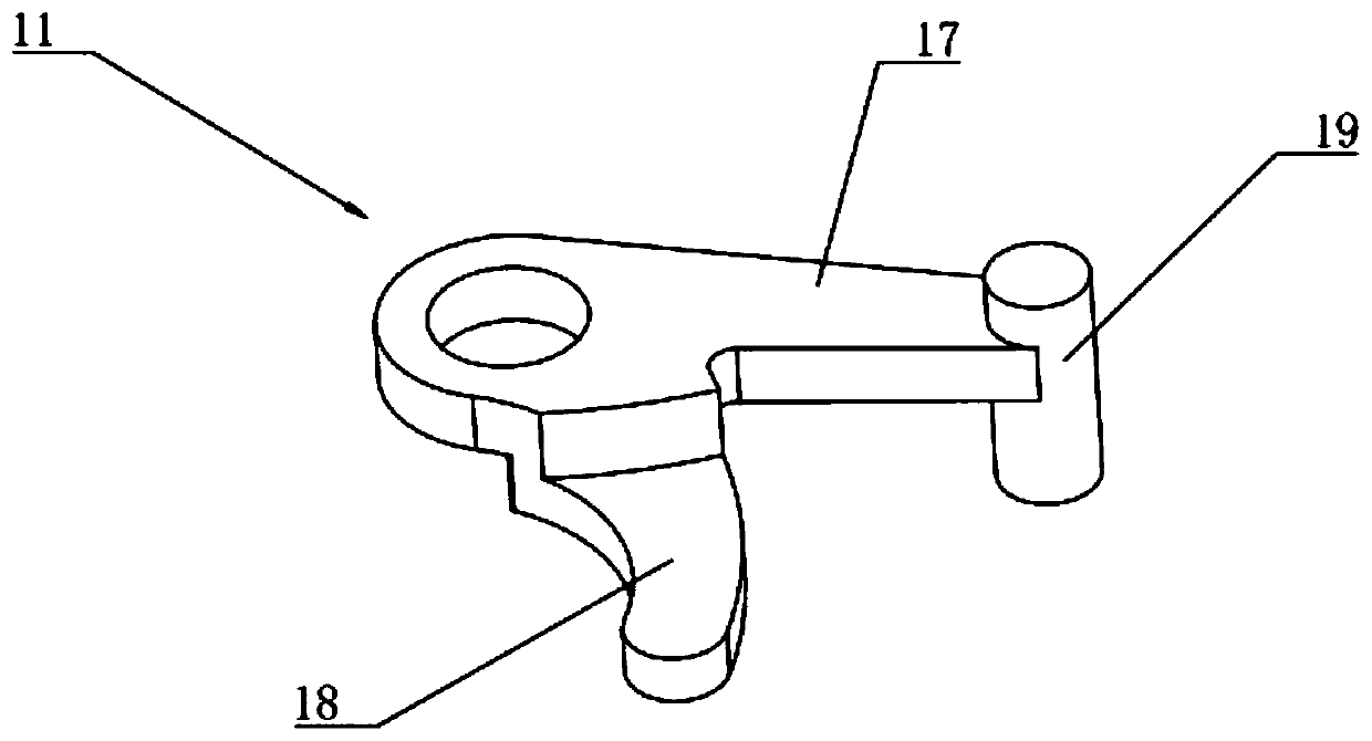
[0091] The main bolt mechanism 28 is a common main bolt structure in the prior art, and the specific structure and working principle are not limited and described here, as they are prior art. The trigger mechanism is arranged on the side of the main bolt mechanism 28 facing the latch mechanism, and includes a trigger member 29 that can contact the trigger portion 18 of the limit member 11 in the limit position, The trigger member 29 is rotatably mounted on the main bolt mechanism 28 through a trigger rotating shaft 31, and a deflection torsion spring is arranged on the trigger rotating shaft 31 t...


PUM


Abstract

The invention belongs to the technical field of mechanical locks, and particularly relates to a latch bolt mechanism and a door lock with the same. The latch bolt mechanism comprises a mounting frame,a latch bolt and a limiting assembly, the limiting assembly is mounted between the latch bolt and the mounting frame, at the locking position of the latch bolt, the limiting assembly can limit rotation of the latch bolt, the limiting assembly is triggered by unlocking operation to be converted into the releasing state from the limiting state of limiting rotation of the latch bolt, and is triggered by door closing operation to return to the limiting state, at the locking position in the limiting state, the action between a triangular body bevel edge middle of the acting end and the locking hole wall of the door opening side on a door frame is the self-locking relation, the latch bolt cannot move towards the locking direction, the latch bolt mechanism can be opened without twisting a door handle, opening is achieved only through triggering the limiting assembly to be in the releasing state through the unlocking operation, through the door closing operation, the limiting assembly returnsto the limiting state, and operation is more easy and convenient.

Description

technical field [0001] The invention belongs to the technical field of mechanical locks, and in particular relates to a bolt mechanism and a door lock with the same. Background technique [0002] Door locks play an important role in ensuring the safety of people and property in the room. According to different unlocking methods, they are usually divided into electronic door locks and mechanical door locks. Among them, the mechanical door lock is unlocked by a key that matches the lock or locked. [0003] In traditional mechanical door locks, the door lock is equipped with a main lock and a bolt mechanism. The main lock on the mechanical lock is controlled by the lock cylinder, and the main lock is opened or closed with a key. The bolt mechanism is controlled by the handle, and the bolt mechanism The function of the door leaf is to position the door leaf on the door frame, which is convenient for simple locking of the door frame, and does not play the role of locking. There...

Claims


Application Information

Patent Timeline
Patent Type & Authority Applications(China)
IPC IPC(8): E05B15/10E05B63/04
CPCE05B15/10E05B15/102E05B63/046
Inventor 吕策
Owner WONLY SECURITY & PROTECTION TECH CO LTD
Why Eureka
Try Eureka