Warmer with mechanical accurate temperature control function

The utility model relates to a heater and a mechanical technology, which is applied in the field of improvement of the heating component mechanism of the heater.

Pending Publication Date: 2020-07-14
NINGBO KADEER ELECTRICAL APPLIANCES
View PDF0 Cites 1 Cited by
  • Summary
  • Abstract
  • Description
  • Claims
  • Application Information

AI Technical Summary

Problems solved by technology

[0003] In order to overcome the inaccurate high temperature control of existing heaters, t

Method used


Image

  • Warmer with mechanical accurate temperature control function
  • Warmer with mechanical accurate temperature control function
  • Warmer with mechanical accurate temperature control function

Examples


Embodiment 1

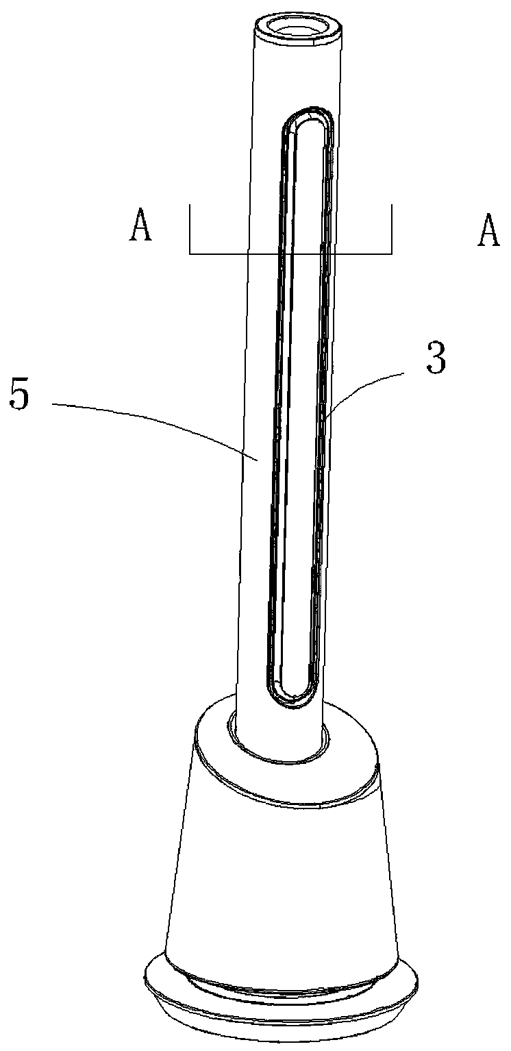
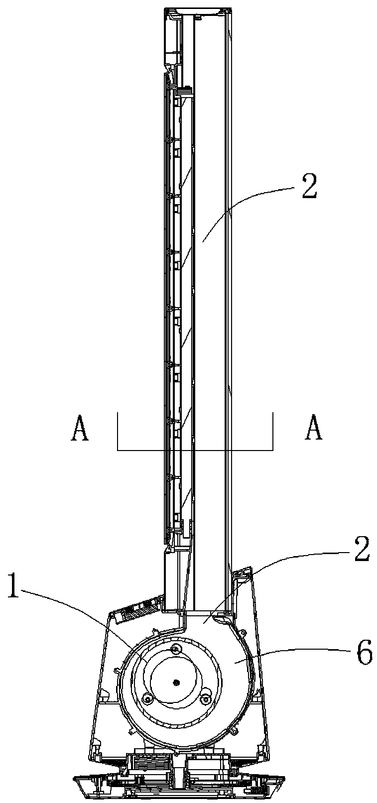
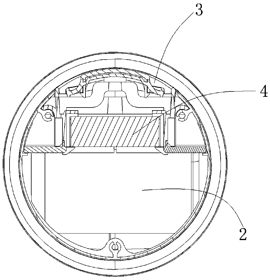
[0027] combined with Figures 1 to 5 , a heater with mechanical precise temperature control function, including a fan 1 and an air chamber 2, the fan 1 is located in the air chamber 2, the front side of the air chamber 2 is provided with an air outlet 3, the air chamber 2 A heating assembly 4 is provided at the front side leading to the air outlet 3, the air outlet 3 is located in front of a bladeless fan column 5 above, the fan 1 is located in the fan chamber 6 below, and the heating assembly 4 is composed of One is composed of several groups of vertically arranged heating grids 7 and a bimetallic group 8 that strings these heating grids 7 together in a horizontal direction. The direction of the bimetallic group 8 is to face the air outlet surface, The heated middle part is bent outwards, and several heat insulating components 9 are provided at the connection between the bimetal sheet group 8 and the heating grid sheet 7 .

[0028] The heat insulation component 9 is a silica...

Embodiment 2

[0031] combined with Figures 4 to 8 , another kind of heater with mechanical precise temperature control function, including a fan 1 and an air chamber 2, the fan 1 is located in the air chamber 2, the front side of the air chamber 2 is provided with an air outlet 3, the air chamber 2 A heating assembly 4 is provided at the front side leading to the air outlet 3, a storage compartment 11 is provided behind the air chamber, and the upper end of the heating assembly 4 is rotatably arranged in the air chamber 2, and the heating assembly 4 rotates Stored in the storage compartment 11 or rotated to the air outlet 3, the heating assembly 4 consists of several groups of vertically arranged heating grids 7 and a bimetallic sheet that strings these heating grids 7 together in a horizontal direction Group 8 is formed, the direction of the bimetal sheet group 8 is to face the air outlet surface, the heated middle part is bent outward, and several heat insulating components 9 are provide...

Embodiment 3

[0035] combined with Figure 4 , attached Figure 5 , attached Figure 6 , attached Figure 9 , there is also a heater with mechanical precise temperature control function, including a fan 1 and an air chamber 2, the fan 1 is located in the air chamber 2, the front side of the air chamber 2 is provided with an air outlet 3, the air chamber 2 A heating assembly 4 is provided at the front side leading to the air outlet 3, and the heating assembly 4 is composed of several groups of vertically arranged heating grid sheets 7 and a pair of horizontally connecting these heating grid sheets 7 together. The metal sheet group 8 is formed, the direction of the bimetal sheet group 8 is to face the air outlet surface, the heated middle part is bent outward, and several heat insulating components 9 are arranged at the connection between the bimetal sheet group 8 and the heating grid sheet.

[0036] The heat insulation component 9 is a silica airgel felt 10, the silica airgel felt 10 is s...


PUM


Abstract

The invention discloses a warmer with a mechanical accurate temperature control function. The warmer comprises a draught fan and an air cavity, wherein the draught fan is located in the air cavity, anair outlet is formed in the front side of the air cavity, a heating assembly is arranged at the position, leading to the air outlet, of the front side of the air cavity, the air outlet is formed in front of an upper bladeless fan stand column, the draught fan is located in a lower draught fan cavity, the heating assembly is composed of a plurality of heating grid pieces which are vertically arranged and a bimetallic strip set which transversely strings the heating grid pieces together, the direction of the bimetallic strip set faces the air outlet face, the heated middle of the bimetallic strip set is bent outwards, and a plurality of heat insulation assemblies are arranged at the joints between the bimetallic strip set and the heating grid pieces. According to the warmer, after the temperature reaches a certain value, the bimetallic strip deforms and bends, the effective air inlet area is reduced, the heating amount is reduced, and automatic temperature control is achieved in a high-temperature area.

Description

technical field [0001] The invention relates to an improvement of a heating assembly mechanism of a heater. Background technique [0002] The heating element of the heater in the prior art heater is generally heated by a similar PTC heating element. When this PTC heating element is used for heating, the PTC heating body will quickly reach a very high temperature due to the rapid temperature rise of the PTC. , so that the outlet temperature of the hot air is in an uncontrollable state. Contents of the invention [0003] In order to overcome the deficiency of inaccurate high temperature control of existing heaters, the present invention provides a heater with a mechanical precise temperature control function. [0004] The technical solution of the present invention to solve this technical problem is: a heater with a mechanical precise temperature control function, including a fan and an air chamber, the fan is located in the air chamber, and an air outlet is provided on the...

Claims


Application Information

Patent Timeline
IPC IPC(8): F24D13/02F24D19/10F24H3/04F24H9/18F24H9/20
CPCF24D13/02F24D19/1096F24D2200/08F24H3/0417F24H9/1872F24H9/2071Y02B10/70
Inventor 沈泽沈建君周韬
Owner NINGBO KADEER ELECTRICAL APPLIANCES
Why Eureka
Try Eureka