Enable switch control circuit
A switch control circuit and resistor technology, applied in electronic switches, electrical components, pulse technology, etc., can solve problems such as jitter, complex circuit structure, etc., and achieve the effect of saving costs and improving reliability
- Summary
- Abstract
- Description
- Claims
- Application Information
AI Technical Summary
Problems solved by technology
Method used
Image

Examples
Embodiment Construction
[0022] Below in conjunction with accompanying drawing, the present invention is described in further detail:
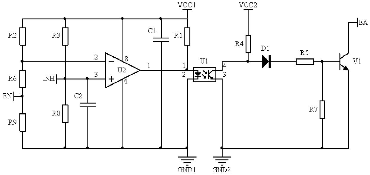
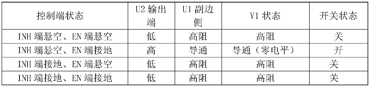
[0023] like figure 1 As shown, the enable switch control circuit of the present invention includes power VCC1, power VCC2, optocoupler U1, comparator U2, capacitor C1, capacitor C2, diode D1, resistors R1-R9 and transistor V1.
[0024] The comparator U2 is used to receive the level change of the input terminal to reflect the required control level signal to the output terminal. The inverting input terminal of the comparator U2 is connected to the enable signal input terminal EN through the resistor R6, and the inverting input terminal is connected through the resistor R6. R2 is connected to the positive terminal of the power supply, and the enable signal input terminal EN is connected to the negative terminal of the power supply of the comparator U2 through the resistor R9; the resistors R2, R6 and R9 are generated at the inverting input terminal of the comparator U2,...
PUM
| Property | Measurement | Unit |
|---|---|---|
| Resistance | aaaaa | aaaaa |
Abstract
Description
Claims
Application Information
 - R&D Engineer
- R&D Manager
- IP Professional
- Industry Leading Data Capabilities
- Powerful AI technology
- Patent DNA Extraction
Browse by: Latest US Patents, China's latest patents, Technical Efficacy Thesaurus, Application Domain, Technology Topic.
© 2024 PatSnap. All rights reserved.Legal|Privacy policy|Modern Slavery Act Transparency Statement|Sitemap