Supercharge Your Innovation With Domain-Expert AI Agents!

Vacuum pump with noise attenuating passage

A technology of vacuum pump and Roots vacuum pump, applied in the field of noise attenuation

Inactive Publication Date: 2020-07-17
INGERSOLL RAND IND U S INC
View PDF8 Cites 0 Cited by
  • Summary
  • Abstract
  • Description
  • Claims
  • Application Information

AI Technical Summary

Problems solved by technology

Some existing systems have various disadvantages with respect to certain applications

Method used


Image

  • Vacuum pump with noise attenuating passage
  • Vacuum pump with noise attenuating passage
  • Vacuum pump with noise attenuating passage

Examples


Embodiment Construction

[0036] For the purposes of promoting an understanding of the principles of the invention, reference will now be made to the embodiments illustrated in the drawings, and specific language will be used to describe the same. It will however be understood that no limitation of the scope of the invention is thereby intended. Any changes and further modifications in the described embodiments and any further applications of the principles of the invention as described herein are contemplated as would normally occur to one skilled in the art to which the invention pertains.

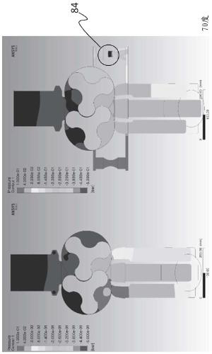
[0037] refer to figure 1 , shows a prior art vacuum roots blower 50 having an inlet 52 configured to provide fluid to a pair of intermeshing rotors 54 and 56, the combined rotation of which in turn Fluid is delivered to outlet 58 for discharge from blower 50 . The pair of intermeshing rotors 54 and 56 are located within a housing 57 . In some forms, rotors 54 and 56 include a two-dimensional cross-sectional pr...


PUM


Abstract

A vacuum roots blower includes a rotor capable of being rotated to capture a gas from an inlet and further rotated to discharge the captured gas from an outlet. The captured gas is held within a pocket formed between lobes of the rotor and the adjacent housing within which the rotor is rotated. The vacuum roots blower includes a pressure relief system capable of delivering a pressure relief gas tothe pocket. The pressure relief system includes a sonic passage structured to produce a choked flow condition as the pressure relief system fills the pocket with pressure relief gas. In one form, thepressure relief gas can be a cooling gas, but other forms, such as ambient air, etc., are also contemplated.

Description

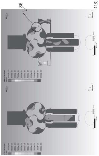
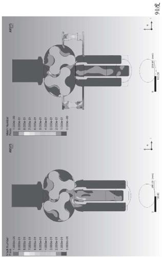
technical field [0001] The present invention relates generally to vacuum roots blowers, and more particularly, but not exclusively, to noise attenuation in vacuum roots blowers. Background technique [0002] Noise generated during operation of vacuum roots blowers remains an area of ​​concern. Some existing systems have various disadvantages with respect to certain applications. Therefore, there remains a need for further contributions in this technical field. Contents of the invention [0003] One embodiment of this invention is a unique pressure relief system for vacuum roots blowers. Other embodiments include apparatus, systems, devices, hardware, methods, and combinations for attenuating noise in vacuum Roots blowers. Other embodiments, forms, features, aspects, benefits and advantages of the present application will become apparent from the description and drawings provided herein. Description of drawings [0004] figure 1 A prior art embodiment of a vacuum Roo...

Claims


Application Information

Patent Timeline
IPC IPC(8): F04C18/12F04C25/02F04C29/06
CPCF04C18/126F04C25/02F04C29/06F04C2270/86F04C2270/13F04C29/042F04C29/065
Inventor M.J.卢卡斯T.霍拉米-佐伊C.道塞特J.B.塔米尼奥G.隆巴尔
Owner INGERSOLL RAND IND U S INC
Features
  • R&D
  • Intellectual Property
  • Life Sciences
  • Materials
  • Tech Scout
  • Unparalleled Data Quality
  • Higher Quality Content
  • 60% Fewer Hallucinations
Learn More