A press-fit mechanism for connecting an optical fiber connector

A technology of optical fiber connector and pressing mechanism, which is applied in the coupling of optical waveguides, instruments, optics, etc., can solve the problems of fiber tearing, inaccurate bending degree, signal loss, etc.

Active Publication Date: 2022-01-25
武汉永鼎光通科技有限公司
View PDF6 Cites 0 Cited by
  • Summary
  • Abstract
  • Description
  • Claims
  • Application Information

AI Technical Summary

Problems solved by technology

[0002] Optical fiber connector is a device for detachable (movable) connection between optical fiber and optical fiber. It precisely butts the two end faces of optical fiber so that the optical energy output by the transmitting optical fiber can be coupled to the receiving optical fiber to the maximum extent. And minimize the impact on the system due to its intervention in the optical link. However, when installing the optical fiber, the common way to fix the optical fiber tube may break the optical fiber when it is pulled, and it needs to be installed during installation. The optical fiber is bent and installed to ensure that the optical fiber is in good contact. Commonly, the optical fiber is bent and installed manually. This kind of bending is not accurate enough. If the bending is too large, it may cause excessive signal loss.

Method used


Image

  • A press-fit mechanism for connecting an optical fiber connector
  • A press-fit mechanism for connecting an optical fiber connector
  • A press-fit mechanism for connecting an optical fiber connector

Examples


Embodiment Construction

[0018] The following will clearly and completely describe the technical solutions in the embodiments of the present invention with reference to the accompanying drawings in the embodiments of the present invention. Obviously, the described embodiments are only some, not all, embodiments of the present invention. Based on the embodiments of the present invention, all other embodiments obtained by persons of ordinary skill in the art without making creative efforts belong to the protection scope of the present invention.

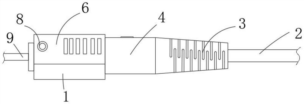
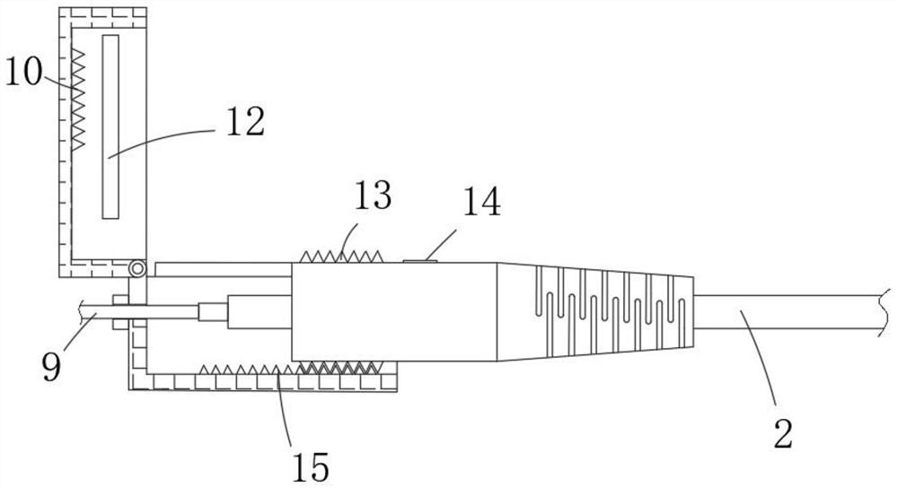
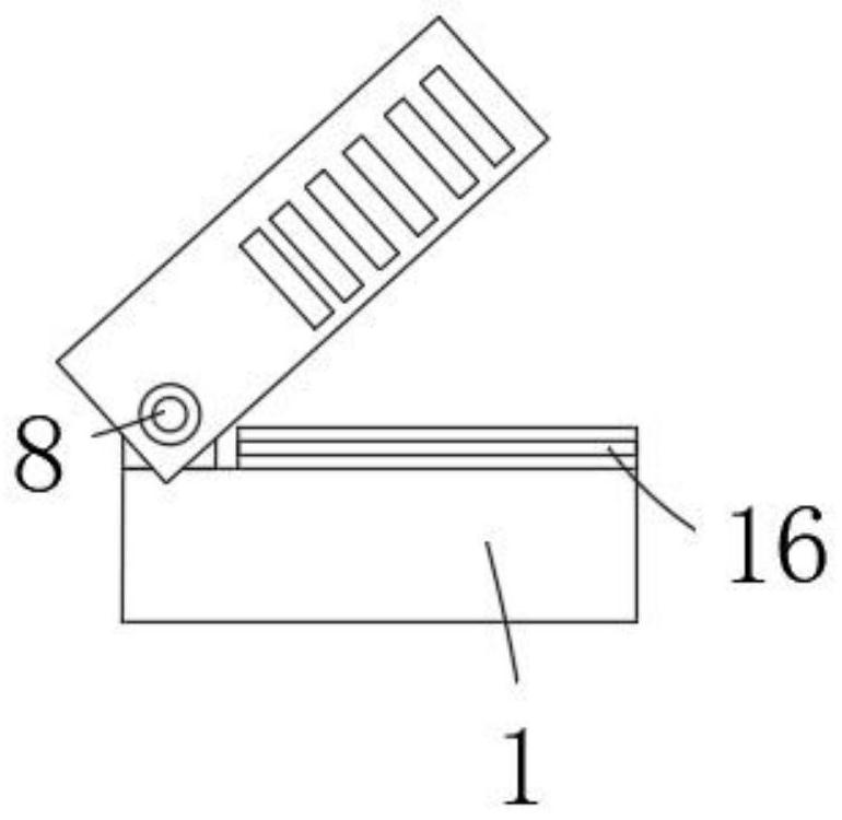
[0019] The present invention provides such Figure 1-4 A pressing mechanism for connecting an optical fiber connector is shown, which includes a cartridge 1 and a limit block 4, and is characterized in that: the inner bottom surface of the cartridge 1 is provided with a lower tooth groove 15, and the left side of the top of the cartridge 1 passes through the rotating shaft 8 is rotationally connected with the rotary cover 6, the inner top surface of the rotary...


PUM


Abstract

The invention discloses a pressing mechanism for optical fiber connector connection. The pressing mechanism for optical fiber connector connection includes a cartridge and a limit block. The inner bottom surface of the cartridge is provided with a lower tooth groove, and the left side of the top of the cartridge is rotationally connected between the rotating shaft and the rotating cover. The inner top surface of the turn cover is provided with an upper tooth groove, and the inner side wall of the turn cover is provided with a raised line, and the top of the cartridge is provided with a groove, and the raised line and the groove are engaged, The top surface and the bottom surface of the limiting block are respectively provided with tooth marks, and the tooth marks are engaged with the upper tooth alveolar and the lower tooth alveolar, and a rubber sleeve is installed on the right end of the limiting block. The inside of the rubber sleeve and the limit block is fixedly installed with an outer tube through the upper rubber ring and the lower rubber ring, and the inside of the outer tube is provided with an optical fiber, and the optical fiber runs through the inside of the cartridge. The optical fiber connection provided by the present invention The press-fit mechanism for connector connection has functions such as bending and fixing optical fibers.

Description

technical field [0001] The invention relates to the technical field of optical fiber connectors, in particular to a pressing mechanism for connecting optical fiber connectors. Background technique [0002] Optical fiber connector is a device for detachable (movable) connection between optical fiber and optical fiber. It precisely butts the two end faces of optical fiber so that the optical energy output by the transmitting optical fiber can be coupled to the receiving optical fiber to the maximum extent. And minimize the impact on the system due to its intervention in the optical link. However, when installing the optical fiber, the common way to fix the optical fiber tube may break the optical fiber when it is pulled, and it needs to be installed during installation. The optical fiber is bent and installed to ensure that the optical fiber is in good contact. Commonly, the optical fiber is bent and installed manually. This kind of bending is not accurate enough. If the bendi...

Claims


Application Information

Patent Timeline
Patent Type & Authority Patents(China)
IPC IPC(8): G02B6/38
CPCG02B6/3898
Inventor 周志勇
Owner 武汉永鼎光通科技有限公司
Why Eureka
Try Eureka