
A threadable shaft hinge structure and electronic equipment

A technology of hinge structure and electronic equipment, applied in the field of shaft hinge structure, can solve the problems that the screen cannot meet the individual needs of users, the hinge design cannot meet the requirements of threading terminal wires, etc., so as to avoid easy damage and large opening and closing angles. Effect

Active Publication Date: 2021-06-25
HEFEI LCFC INFORMATION TECH
View PDF8 Cites 0 Cited by
  • Summary
  • Abstract
  • Description
  • Claims
  • Application Information

AI Technical Summary

Problems solved by technology

At present, most of the designs are threaded through hinges. As the demand for notebook computers tends to be lighter and thinner, the extremely small hinge design can no longer meet the requirements for threading terminal wires. The problem of passing the terminal wire directly to the system end without passing through the hinge
[0003] In addition, the newer design for threading the terminal wires currently includes adjusting the position of the terminal wires from the rotating shaft. However, such a structural design causes the terminal wires to be exposed or the opening angle of the display screen is only about 120 degrees, which can be seen when the screen is opened. Angle can not meet the individual needs of users

Method used


Image

  • A threadable shaft hinge structure and electronic equipment
  • A threadable shaft hinge structure and electronic equipment
  • A threadable shaft hinge structure and electronic equipment

Examples


Embodiment Construction

[0032] Below, specific embodiments of the present invention will be described in detail in conjunction with the accompanying drawings, but they are not intended to limit the present invention. In order to enable those skilled in the art to better understand the technical solutions of the present disclosure, the present disclosure will be described in detail below in conjunction with the accompanying drawings and specific embodiments. Embodiments of the present disclosure will be described in further detail below in conjunction with the accompanying drawings and specific embodiments, but are not intended to limit the present disclosure.

[0033] All terms (including technical terms or scientific terms) used in the present disclosure have the same meaning as understood by one of ordinary skill in the art to which the present disclosure belongs, unless otherwise specifically defined. It should also be understood that terms defined in, for example, general-purpose dictionaries sho...


PUM


Abstract

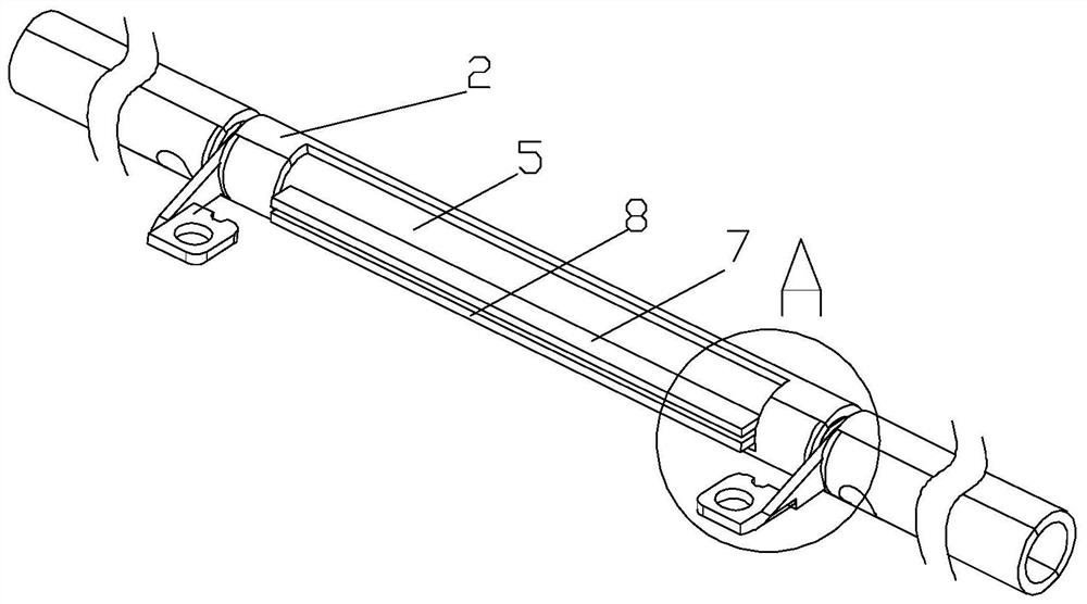
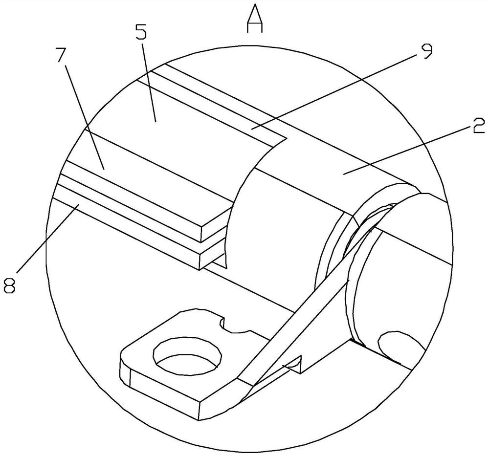
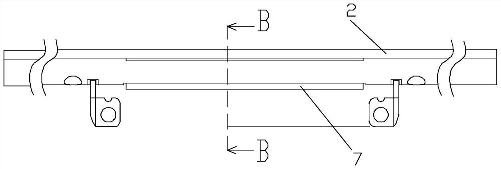
The present invention provides a shaft hinge structure that can be threaded, including a hollow shaft and an outer sleeve that are arranged and rotated from the inside to the outside; the hollow shaft is provided with a first through hole, a second through hole, a first protrusion and an outer sleeve. The second protrusion; wherein, the first through hole and the second through hole respectively pass through the side wall of the hollow shaft in the radial direction of the hollow shaft; the first protrusion and the second The two protrusions are arranged opposite to each other along the axial direction of the hollow shaft, and extend radially outward from the inner wall of the first through hole; the outer sleeve is provided with a third through hole and a fourth through hole, respectively penetrating through the side wall of the outer sleeve; the first protruding portion and the second protruding portion protrude outward through the third through hole; the threadable shaft hinge structure of the present invention is When the electronic equipment is thinner and lighter, it can meet the requirement of not passing through the terminal wire through the hinge, and directly pass the terminal wire from the display screen to the system.

Description

technical field [0001] The invention belongs to the field of electronic equipment, in particular to a threadable shaft hinge structure. Background technique [0002] Existing notebook computers all have the requirement of passing terminal wires from the display side to the system side. At present, most of the designs are threaded through hinges. As the demand for notebook computers tends to be lighter and thinner, the extremely small hinge design can no longer meet the requirements for threading terminal wires. The problem of passing the terminal wire directly to the system end without passing through the hinge. [0003] In addition, the newer design for threading the terminal wires currently includes adjusting the position of the terminal wires from the rotating shaft. However, such a structural design causes the terminal wires to be exposed or the opening angle of the display screen is only about 120 degrees, which can be seen when the screen is opened. Angle also can no...

Claims


Application Information

Patent Timeline
Patent Type & Authority Patents(China)
IPC IPC(8): G06F1/16
CPCG06F1/1616G06F1/1681
Inventor 邱宣谚王国纶吴纮纮
Owner HEFEI LCFC INFORMATION TECH
Learn More