Electric connector

An electrical connector and electrical connection technology, which is applied in the direction of connection, two-part connection device, circuit, etc., can solve problems such as poor contact of electrical connectors, and achieve the effects of avoiding poor contact, preventing loosening, and strong applicability

Active Publication Date: 2020-07-17
REPOWER TECH CO LTD
View PDF5 Cites 2 Cited by
  • Summary
  • Abstract
  • Description
  • Claims
  • Application Information

AI Technical Summary

Problems solved by technology

[0003] The purpose of the present invention is to provide an electrical connector, which aims to solve the technical problem that the electrical connector in the prior art is prone to poor contact during connection

Method used


Image

  • Electric connector
  • Electric connector
  • Electric connector

Examples


Embodiment 1

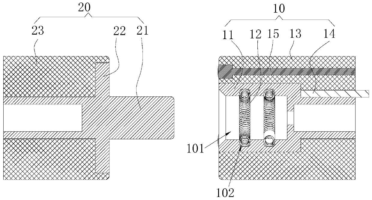
[0021] Please refer to figure 1 , the present invention provides an electrical connector, which includes an electrical connection socket 10 and an electrical connection pin 20 capable of docking with the electrical connection socket 10 . The electrical connection socket 10 and the electrical connection pin 20 are respectively connected to a power source and an electrical device through wires.

[0022] Among them, the electrical connection socket 10 at least includes a conductive seat 11 capable of conducting electricity and a resisting spring 12. The conductive seat 11 is provided with an insertion groove 101, and the resisting spring 12 is connected to the groove side wall of the inserting groove 101. The resisting spring 12 is elastic and can conduct electricity. The collision spring 12 may be block-shaped, or strip-shaped along the axial direction of the insertion groove 101 , or arc-shaped, ring-shaped or helical-shaped along the groove sidewall of the insertion groove 10...

Embodiment 2

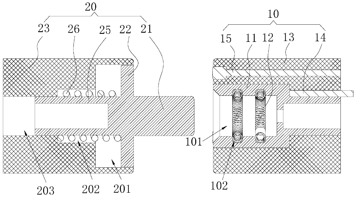
[0034] Please refer to figure 2 , Embodiment 2 of the present invention provides an electrical connector. Compared with Embodiment 1, the difference is that the electrical connection pin 20 also includes a side connected to the pin 21 away from its extending direction and facing away from the pin. The extension piece 25 extending on one side of the extension direction of 21 and the elastic piece 26 sleeved on the extension piece 25, the second insulator 23 has a first groove 201 for sliding the lug 22 toward the extension direction of the pin 21, The first groove 201 is provided with a second groove 202 at the bottom of the groove, and the second groove 202 is provided with a third groove 203 at the bottom of the groove for the sliding connection of the extension member 25, that is to say, the first groove 201 and the opening direction of the third groove 203 are the same, the first groove 201, the second groove 202 and the third groove 203 form a stepped structure, and one e...

Embodiment 3

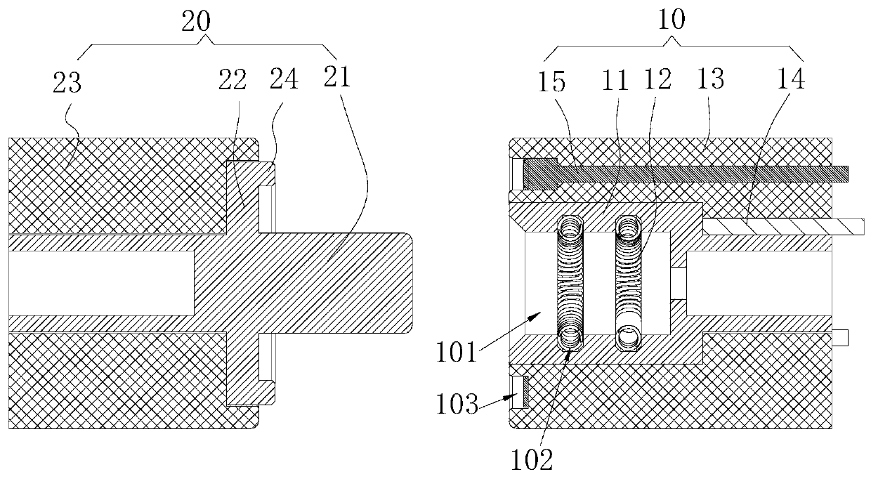
[0036] Please refer to image 3 Embodiment 2 of the present invention provides an electrical connector. Compared with Embodiment 1, the difference lies in that the first insulator 13 is provided with a connecting groove 103 on its end surface facing the opening direction of the insertion groove 101, and the second The signal transmission line 15 is connected to the bottom of the connection groove 103. The electrical connection pin 20 also includes a plug-in block 24 connected to the lug 22 and extending toward the extension direction of the pin 21. The plug-in block 24 can be inserted in the pin 21. When inserted into the slot 101 , it is plugged into the connection slot 103 and electrically connected to the second signal transmission line 15 . In this way, the second signal transmission line 15 can be hidden in the connection groove 103 to avoid scratches or wear, and ensure normal connection with the first signal transmission line 14 . The connection groove 103 also plays a...


PUM


Abstract

The invention provides an electric connector which comprises an electric connection socket and an electric connection contact pin. The electric connection socket at least comprises a conductive base capable of conducting electricity and an abutting spring, the conductive base is provided with a plugging groove, and the abutting spring is connected to the groove side wall of the plugging groove, has elasticity and can conduct electricity. The electric connection contact pin at least comprises a contact pin which can conduct electricity, extends outwards and can be inserted into the plugging groove in a matched manner, wherein the abutting spring can electrically conduct the contact pin and the conductive base after the contact pin is plugged in the plugging groove. According to the invention, by arranging the conductive and elastic abutting spring in the plugging groove, the abutting spring elastically deforms and clings to the outer wall of the contact pin when the contact pin is plugged in the plugging groove, thereby enabling the contact pin to be tightly connected with the conductive base, preventing loosening, avoiding the poor contact, and eliminating potential safety hazards.

Description

technical field [0001] The invention belongs to the technical field of electric appliance connection equipment, and in particular relates to an electric connector. Background technique [0002] When the equipment operates with high power, it often requires a large current, and the electrical connectors used for large current conduction often have poor contact during connection due to processing errors or excessive use time, which makes the equipment unable to work normally. , and even pose a security risk. Contents of the invention [0003] The object of the present invention is to provide an electrical connector, aiming to solve the technical problem that the electrical connector is prone to poor contact during connection in the prior art. [0004] The present invention is achieved in this way, an electrical connector, comprising: [0005] The electrical connection socket at least includes a conductive seat capable of conducting electricity and a resisting spring capabl...

Claims


Application Information

Patent Timeline
Patent Type & Authority Applications(China)
IPC IPC(8): H01R13/187H01R24/00
CPCH01R13/187H01R24/00
Inventor 毛广甫
Owner REPOWER TECH CO LTD
Why Eureka
Try Eureka