Valve seat assembly, ball valve and assembling method of valve seat assembly

A technology for valve seats and components, applied to valve devices, engine components, cocks including cut-off devices, etc., can solve problems such as valve sealing failure, valve seat falling off, and valve seat being easily crushed

Pending Publication Date: 2019-06-18
NEWAY VALVE SUZHOU
View PDF1 Cites 0 Cited by
  • Summary
  • Abstract
  • Description
  • Claims
  • Application Information

AI Technical Summary

Problems solved by technology

[0006] Therefore, the technical problem to be solved by the present invention is that in the valve seat assembly in the prior art, after the valve is opened and closed many times, the valve seat is easy to fall off from the first annular groove of the retainer, resulting in failure of the valve seal and pressing in. The defect that the valve seat is easily crushed when the valve seat pressure is too large

Method used


Image

  • Valve seat assembly, ball valve and assembling method of valve seat assembly
  • Valve seat assembly, ball valve and assembling method of valve seat assembly
  • Valve seat assembly, ball valve and assembling method of valve seat assembly

Examples


Embodiment 1

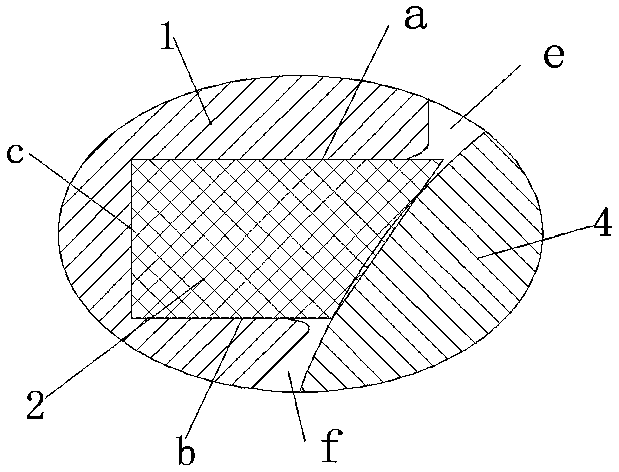
[0048] This embodiment provides a valve seat assembly, such as Figure 2 to Figure 8 As shown, it includes a retainer 1, a valve seat 2 and an expansion ring 3.

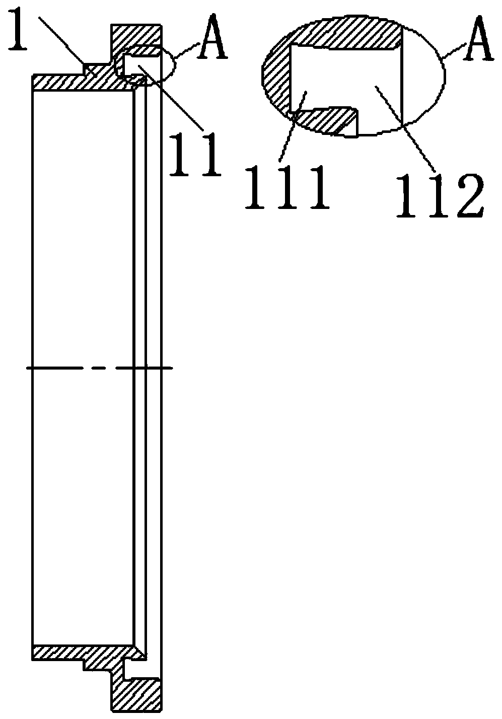
[0049] Among them, such as figure 2 , Figure 5 to Figure 8 As shown, the axial end surface of the fixture 1 is provided with a first annular groove 11 sunken inward, and the first annular groove 11 includes a flared section 111 and a small-diameter end fixed to the flared section 111 along its axial direction. The straight section 112 on the top; the longitudinal section shape of the flaring section 111 is a dovetail shape, the fixer is circular, and the fixer is provided with a boss on the side away from the first annular groove in its axial direction, through which the boss will The retainer is fixed on the inner wall of the valve body; the longitudinal section of the expansion ring 3 is dovetail-shaped, the flared section 111 of the first annular groove 11 corresponds to the expansion ring 3, and the straight ...

Embodiment 2

[0063] This embodiment provides a ball valve, such as Figure 9 As shown, it includes the valve seat assembly, valve stem and valve ball 4 in Embodiment 1.

[0064] Wherein, the valve stem is fixed on the valve ball 4, and the rotation of the valve stem drives the rotation of the valve ball 4 to realize the closing or opening of the ball valve. When the ball valve is closed, the sealing surface of the valve seat assembly is in close contact with the outer wall of the valve ball 4 to form a sealing pair to block the medium circulating in the valve cavity; when the valve is opened, the sealing surface of the valve seat assembly and the outer wall of the valve ball 4 The wall surface is separated to realize the opening of the ball valve, and the medium can circulate in the valve cavity.

[0065] In the ball valve with this structure, the valve seat 2 will not fall off from the first annular groove 11 of the retainer 1, and the valve has reliable sealing and long service life.

Embodiment 3

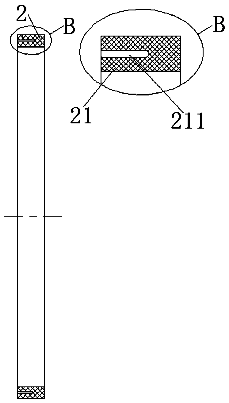
[0067] This embodiment provides an assembly method of a valve seat assembly, such as Figure 5 to Figure 8 As shown, it includes the following steps: first insert the part of the expansion ring 3 facing the sealing surface of the valve seat 2 into the notch of the second annular groove 211 of the valve seat 2 to form a combination; then insert the valve seat 2 The whole combination with the expansion ring 3 is first installed in the first annular groove 11 of the holder 1, so that the end surface of the expansion ring 3 facing away from the sealing surface of the valve seat 2 abuts against the groove of the first annular groove 11 On the bottom, the mounting end 21 of the valve seat 2 partially extends into the first annular groove 11; then the valve seat 2 is pressed into the first annular groove 11 from the notch of the first annular groove 11 toward the bottom of the first annular groove 11. In an annular groove 11, the second annular groove 211 of the valve seat 2 is gradu...


PUM


Abstract

The invention discloses a valve seat assembly, a ball valve and an assembling method of the valve seat assembly. The valve seat assembly comprises a fixator, a valve seat and a distracting ring. The ball valve comprises the valve seat assembly, a valve rod and a valve ball. The assembling method comprises the steps that the distracting ring is firstly inserted into the valve seat to form a combination; then the combination is mounted in a first annular groove of the fixator, and the end face of the distracting ring abuts against the groove bottom; and finally the valve seat is pressed into thefirst annular groove, so that the end face of the valve seat abuts against the groove bottom. According to the valve seat assembly of the structure, shaking of the valve seat in the first annular groove can be reduced, the valve seat is effectively prevented from being separated out of the first groove, and sealing between the valve seat and valve ball is guaranteed. Before the valve seat and thefirst annular groove are inserted in place, the width of the valve seat is equivalent to that of the first annular groove, and interference is avoided; the valve seat is pressed into the fixator through a press, the acting force is not too large, and the end, exposed out of the first annular groove, of the valve seat can be effectively prevented from being crushed.

Description

technical field [0001] The invention relates to the technical field of valves, in particular to a valve seat assembly, a ball valve and an assembly method for the valve seat assembly. Background technique [0002] In the valve of the prior art, a retainer is provided between the valve seat and the valve body, the seat is provided on the retainer, and a sealing pair is formed between the valve seat and the valve disc. For example, when the valve is a ball valve, a sealing pair is formed between the valve seat and the ball, or when the valve is a globe valve, a sealing pair is formed between the valve seat and the disc. [0003] Most of the fixing methods between the retainer and the valve seat in the prior art are as disclosed in Chinese patent document CN202790647U in a large-diameter top-mounted fixed ball valve, such as figure 1 As shown, there is an annular groove on the end surface of the retainer body facing the ball, the groove width of the first annular groove is con...

Claims


Application Information

Patent Timeline
Patent Type & Authority Applications(China)
IPC IPC(8): F16K5/08F16K5/06F16K5/20
Inventor 陈军宋世君
Owner NEWAY VALVE SUZHOU
Why Eureka
Try Eureka