Battery grouping framework based on flexible connection and redundancy
A flexible connection and battery module technology, applied in battery circuit devices, secondary battery charging/discharging, arrangement of multiple synchronous batteries, etc., can solve the problem of no voltage equalization control, high cost, overvoltage and overcurrent protection functions Insufficient and other problems, to achieve the effect of efficient operation
- Summary
- Abstract
- Description
- Claims
- Application Information
AI Technical Summary
Problems solved by technology
Method used
Image

Examples
Embodiment 1
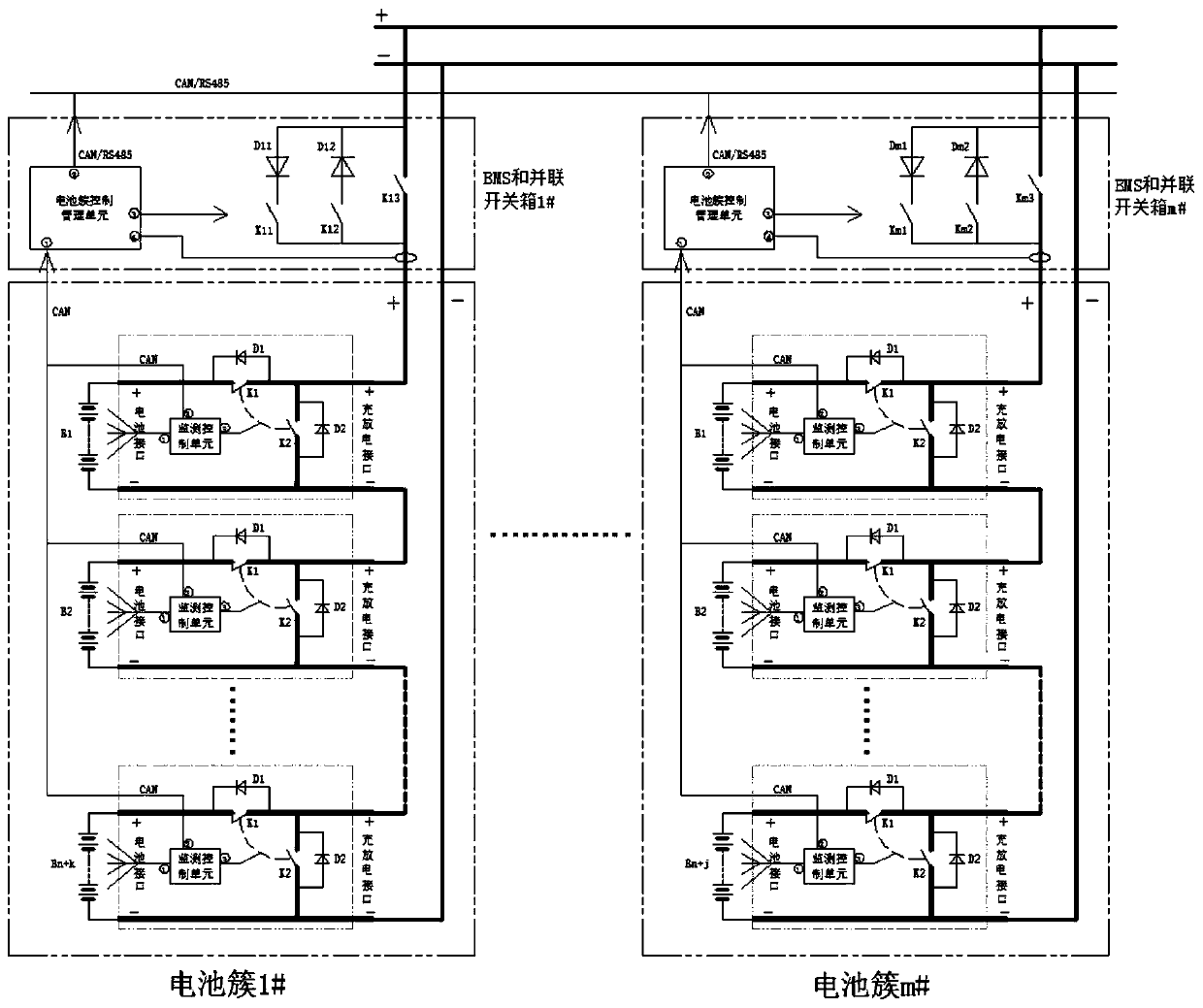
[0043] Example 1, seefigure 1 , The battery group architecture based on flexible connection modules and redundancy includes: battery cluster 1#-m#, BMS and parallel switch box 1#-m#, DC bus, etc. Battery cluster 1# is connected to the DC bus through BMS and parallel switch box 1#. Similarly, battery cluster m# is connected to the DC bus through BMS and parallel switch box m#. Wherein, the m battery clusters have the same structure, but the number of battery modules may be different. n+k battery modules are connected in series through n+k flexible connection modules ("+" and "-" of adjacent flexible connection modules are connected) to form a battery cluster, among which n battery modules must be used to establish the DC bus voltage The number of k battery modules is redundant; the battery modules in different battery clusters can be of different batches, voltages or manufacturers, and the values of n and k in different battery clusters can also be different, but its The val...
Embodiment 2
[0056] Choice of n, k and m values.
[0057] The value of n is determined by the DC bus voltage and the terminal voltage of the battery module. If the DC bus voltage is 1000V and the nominal terminal voltage of the battery module is 48V, then n=1000 / 48=20.8, and the value is 21. The value of k is determined by the battery rest time and the interval between turns. If the battery resting time is 30 minutes and the interval between turns is 15 minutes, then k=30 / 15=2, and the minimum value of k is 2. Similarly, if the interval between turns is 10 minutes, then k=3. The larger the value of k, the more the number of strings, and the larger the capacity of the battery cluster.
[0058] m represents the number of battery clusters, which is positively related to the group capacity and has nothing to do with the architecture itself.
Embodiment 3
[0060] Input and exit of the battery module.
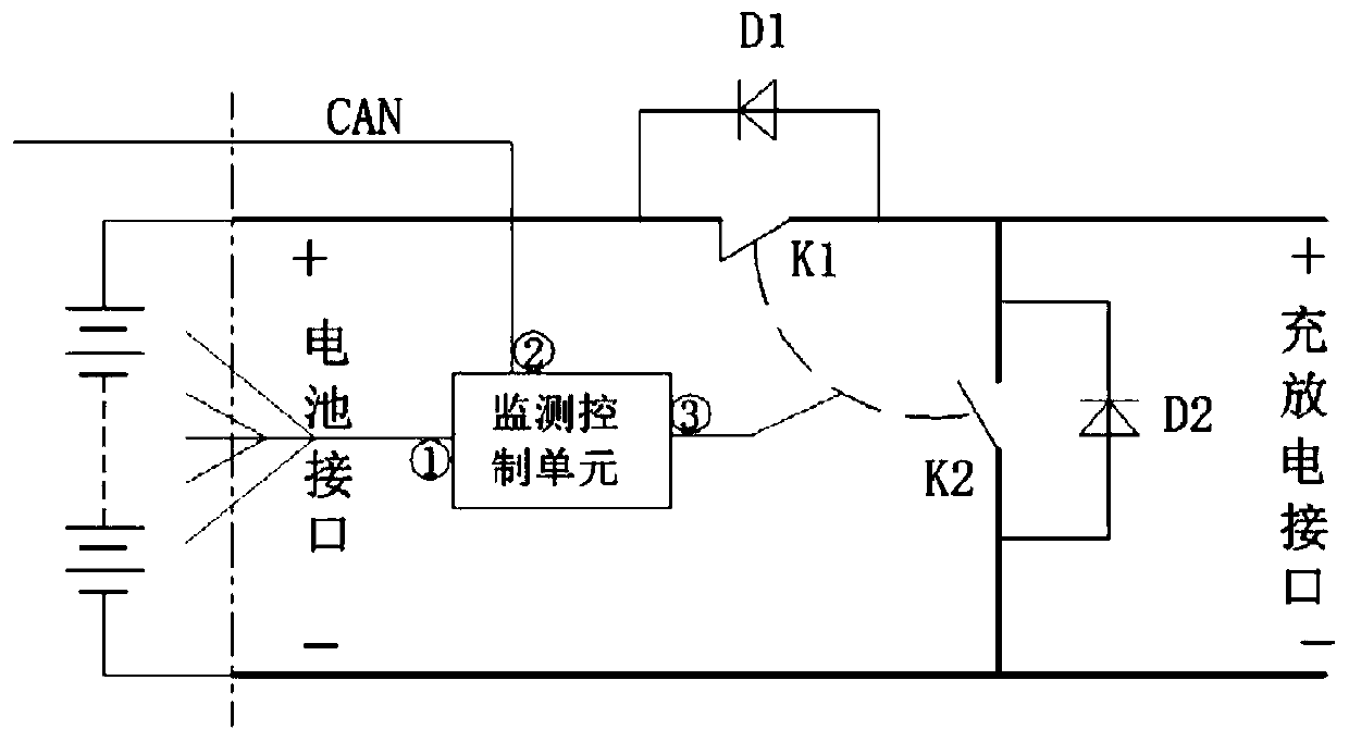
[0061] The battery cluster control management unit controls the input and withdrawal of the battery modules of the cluster through the flexible connection module according to the control strategy. Flexible connection module topologies such as figure 2 As shown, it includes: charge and discharge switch (K1), charge diode (D1), bypass switch (K2), bypass diode (D2) and monitoring control unit, charge and discharge switch (K1) and bypass switch (K2) There shall be mechanical or logical interlocks. Among them, one end of the charging and discharging switch (K1) is connected to the "+" of the battery interface, and the other end is connected to the "+" of the charging and discharging interface to realize the charging and discharging of the battery module; one end of the bypass switch (K2) is connected to the charging and discharging interface. The "+" of the charging and discharging interface is connected to the other end, and the b...
PUM
 Abstract
Description
Claims
Application Information
 - R&D Engineer
- R&D Manager
- IP Professional
- Industry Leading Data Capabilities
- Powerful AI technology
- Patent DNA Extraction
Browse by: Latest US Patents, China's latest patents, Technical Efficacy Thesaurus, Application Domain, Technology Topic.
© 2024 PatSnap. All rights reserved.Legal|Privacy policy|Modern Slavery Act Transparency Statement|Sitemap