
Indicator drive circuit for realizing five attack angle states of airplane

A technology for driving circuits and indicators, applied in the field of aircraft lighting, can solve the problems of single receiving mode and display state, and achieve the effects of avoiding stall danger, simple topology structure, and avoiding interference.

Inactive Publication Date: 2020-07-21
SHANGHAI AVIATION ELECTRIC
View PDF0 Cites 0 Cited by
  • Summary
  • Abstract
  • Description
  • Claims
  • Application Information

AI Technical Summary

Problems solved by technology

Single receiving method and display status

Method used


Image

  • Indicator drive circuit for realizing five attack angle states of airplane
  • Indicator drive circuit for realizing five attack angle states of airplane
  • Indicator drive circuit for realizing five attack angle states of airplane

Examples


Embodiment Construction

[0013] The present invention will be described in detail below in conjunction with the accompanying drawings and embodiments.

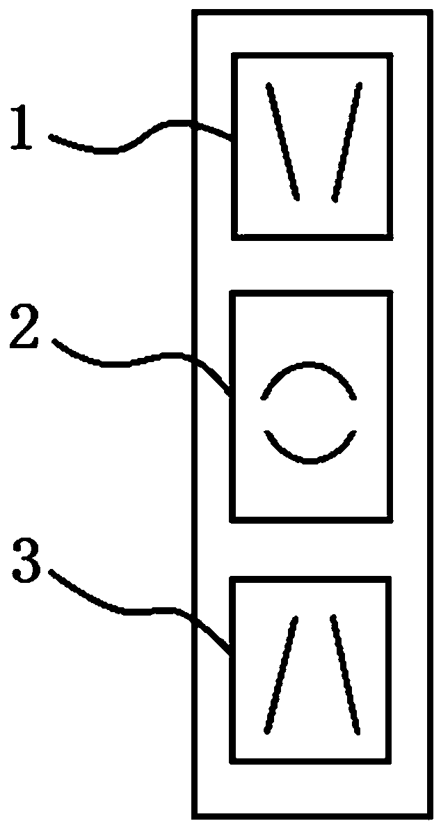
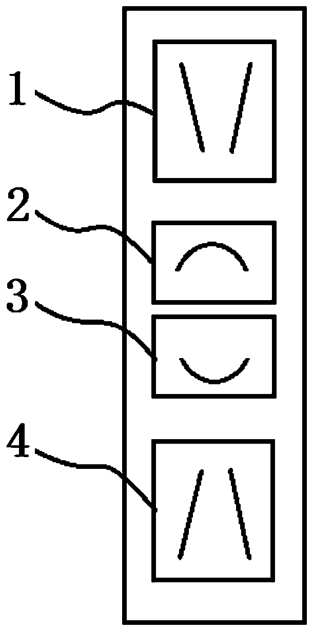
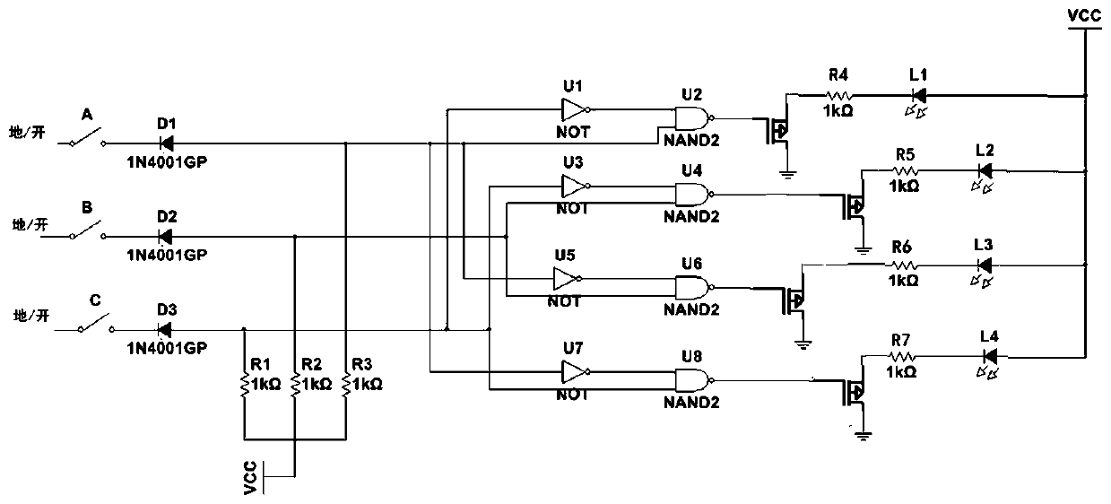
[0014] See figure 2 and 3 , the indicator driving circuit structure for realizing five kinds of angle-of-attack states of the aircraft is characterized in that it includes indicator lights L1, indicator lights L2, indicator lights L3 and indicator lights L4, and utilizes the large signal A of the angle of attack and the normal signal B of the angle of attack And the different combinations of the small angle-of-attack signal C respectively logically control the light and dark of the indicator light L1, indicator light L2, indicator light L3 and indicator light L4, so as to realize a large angle of attack, a large angle of attack, and a normal angle of attack , small angle of attack and five states of small angle of attack.

[0015] Boolean logic is: L1=A +AB =A , L2=AB + B =B ,L3= B + BC= B,L4= C+ BC= c.

[0016] The log...


PUM


Abstract

The invention particularly relates to an indicator drive circuit structure for realizing five attack angle states of an airplane. The structure comprises an indicating lamp L1 (identification symbol:'V'), an indicating lamp L2 (identification symbol: '('), an indicating lamp L3 (identification symbol: ')') and an indicating lamp L4 (identification symbol: 'inverted V'). The brightness of the indicating lamp L1, the indicating lamp L2, the indicating lamp L3 and the indicating lamp L4 is logically controlled respectively by using different combination modes of the attack angle large signal A,the attack angle normal signal B and the attack angle small signal C, so that five states of large attack angle, relatively large attack angle, normal attack angle, relatively small attack angle and small attack angle are realized. The beneficial effects of the invention are that the whole circuit achieves five indication states, provides more accurate attack angle information for a pilot, adjuststhe attack angle in time in the take-off and landing and flight processes, guarantees the normal operation of take-off and landing, avoids the stall risk of a critical attack angle, and guarantees the stable flight.

Description

technical field [0001] The invention relates to the field of aircraft lighting, and relates to a driving circuit for realizing indications of five angles of attack states of an aircraft. Background technique [0002] The angle-of-attack indicator is a kind of cockpit instrument that indicates the angle of attack of the aircraft. It can provide a visual aid for the pilot to prevent the aircraft from malfunctioning during critical stages of flight. The angle-of-attack indicator can help avoid stalls due to stall Can occur at any speed, and stall judgment based on speed alone is not reliable. For a certain aircraft configuration, the aircraft always stalls at the critical angle of attack. Without an AOA indicator, AOA is difficult for the pilot to perceive. The angle of attack indicator can be linked to the airspeed and stall warning systems to provide an alert for the pilot's attention. [0003] See figure 1 , most of the existing angle-of-attack indicators have three indi...

Claims


Application Information

Patent Timeline
Patent Type & Authority Applications(China)
IPC IPC(8): B64D43/00
CPCB64D43/00
Inventor 华雯怡段敬琳
Owner SHANGHAI AVIATION ELECTRIC
Learn More