Air hole sleeve inlay device and equipment
A technology of air hole sleeve and preset direction, applied in metal processing equipment, metal processing, manufacturing tools, etc., can solve the problems of low efficiency of pattern block or side plate air hole sleeve, etc.
- Summary
- Abstract
- Description
- Claims
- Application Information
AI Technical Summary
Problems solved by technology
Method used
Image
Examples
Example Embodiment
[0048] Example 1
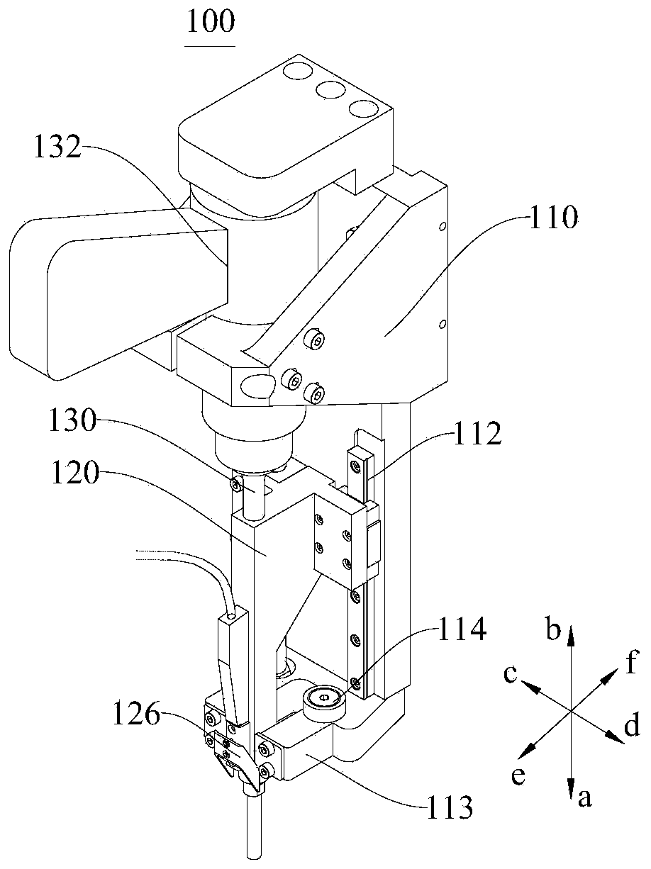
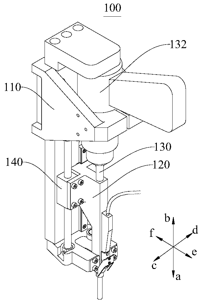
[0049] figure 1 It is a schematic diagram of a first perspective view of the vent sleeve inlay device 100 in Embodiment 1 of the present invention; figure 2 It is a schematic diagram of a second perspective of the vent sleeve inlay device 100 in Embodiment 1 of the present invention;
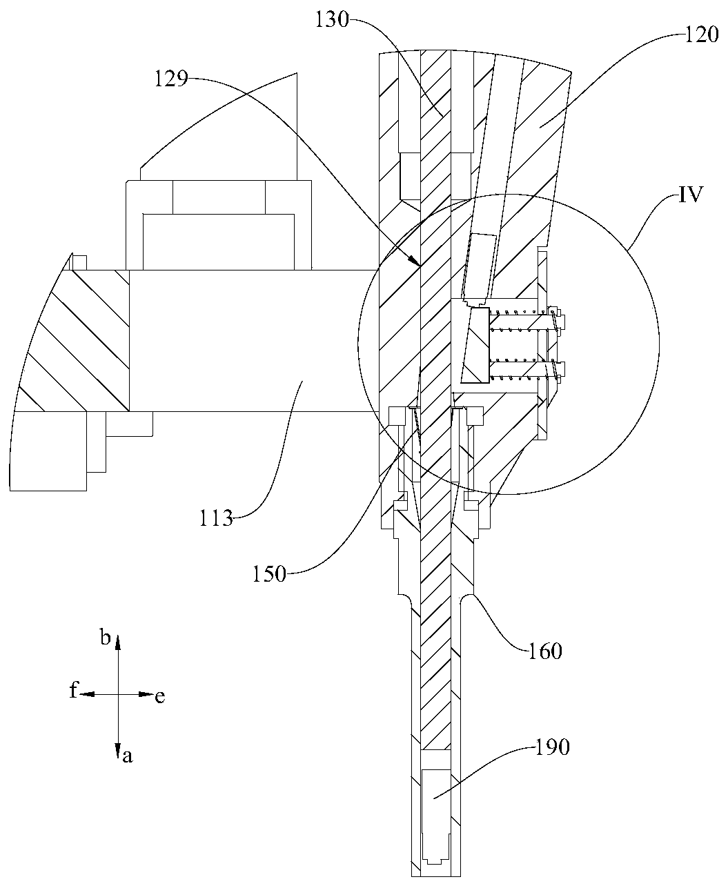
[0050] image 3 It is a partial cross-sectional view of the vent sleeve inserting device 100 in Embodiment 1 of the present invention. Please refer to Figure 1 to Figure 3 This embodiment provides a vent sleeve inserting device 100 for inserting a vent sleeve 190 into the exhaust hole of a tire mold. The air hole sleeve inserting device 100 includes a fixed seat 110, a sliding seat 120, a punch 130, and a return mechanism.
[0051] One end of the punch 130 is connected to the fixing seat 110 through the power member 132, and the other end of the punch 130 extends in a preset direction (that is, the direction of the air hole sleeve 190, the direction a in the figure). The power me...
Example Embodiment
[0069] Example 2
[0070] Figure 8 It is a schematic diagram of the structure of the vent sleeve inlay device 100 in Embodiment 2 of the present invention. Please refer to Figure 8 This embodiment provides a vent sleeve inlay device 100, which is substantially the same as the device of the first embodiment. The difference is that the vent sleeve inlay device 100 in this embodiment further includes a base 180 and a second driving portion 185. The base 180 A second guide rail 184 is provided on the fixing base 110, and the fixing seat 110 is slidably fitted with the base 180 through the second guide rail 184, and can move in the ab direction relative to the base 180. The second driving part 185 is used to drive the fixing base 110 at least in a preset direction ( a direction) moving upward, preferably the second driving part 185 can drive the fixing base 110 to move in the ab direction. In this embodiment, the second driving part 185 is similar to the first driving part 140, and...
Example Embodiment
[0074] Example 3
[0075] Picture 9 It is a schematic diagram of the structure of the vent sleeve inlay device 100 in Embodiment 3 of the present invention. Please refer to Picture 9 This embodiment provides a vent sleeve inlay device 100, which is substantially the same as the device in Embodiment 2, except that the power part 132 in this embodiment is a cylinder or a linear motor. In addition, the power element 132 is fixed to the base 180, and its output end (such as a piston rod) is connected to the fixing base 110, and the fixing base 110 is fixedly connected to the punch 130. At this time, it is equivalent to the connection between the power part 132 and the punch 130 through the force measuring device 134, which can detect the pressure between the power part 132 and the punch 130 in real time, so that the detected pressure can be used to determine whether the air hole sleeve is Move the mosaic to the corresponding position. In this embodiment, the displacement of the f...
PUM
 Abstract
Description
Claims
Application Information
 - R&D
- Intellectual Property
- Life Sciences
- Materials
- Tech Scout
- Unparalleled Data Quality
- Higher Quality Content
- 60% Fewer Hallucinations
Browse by: Latest US Patents, China's latest patents, Technical Efficacy Thesaurus, Application Domain, Technology Topic, Popular Technical Reports.
© 2025 PatSnap. All rights reserved.Legal|Privacy policy|Modern Slavery Act Transparency Statement|Sitemap|About US| Contact US: help@patsnap.com


