Metallographic sample preparation inlaying tool and inlaying method
A metallographic sample preparation and tooling technology, which is applied in the field of metallographic inlays, can solve the problems of large tolerance between the sample axis and the observed surface, difficulty in controlling the verticality of wire samples, and observation artifacts, etc., to reduce metallographic Phase illusion, good applicability, and efficiency-enhancing effects
- Summary
- Abstract
- Description
- Claims
- Application Information
AI Technical Summary
Problems solved by technology
Method used
Image
Examples
Embodiment 1
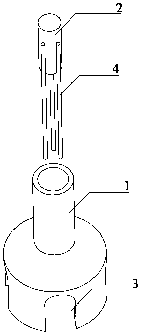
[0047] see figure 1 As shown, the present invention provides an inlay tool for metallographic sample preparation, which can fix the wire to be inlaid perpendicular to the bottom surface of the inlay mold in a clamping manner, thereby reducing the occurrence of false images.
[0048] Specifically, the tooling structure includes: a main body 1 with an upper opening and a lower opening, and a crimping pin 2 .
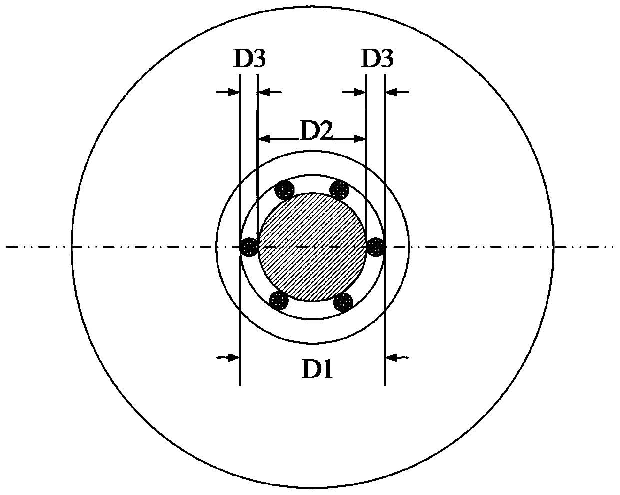
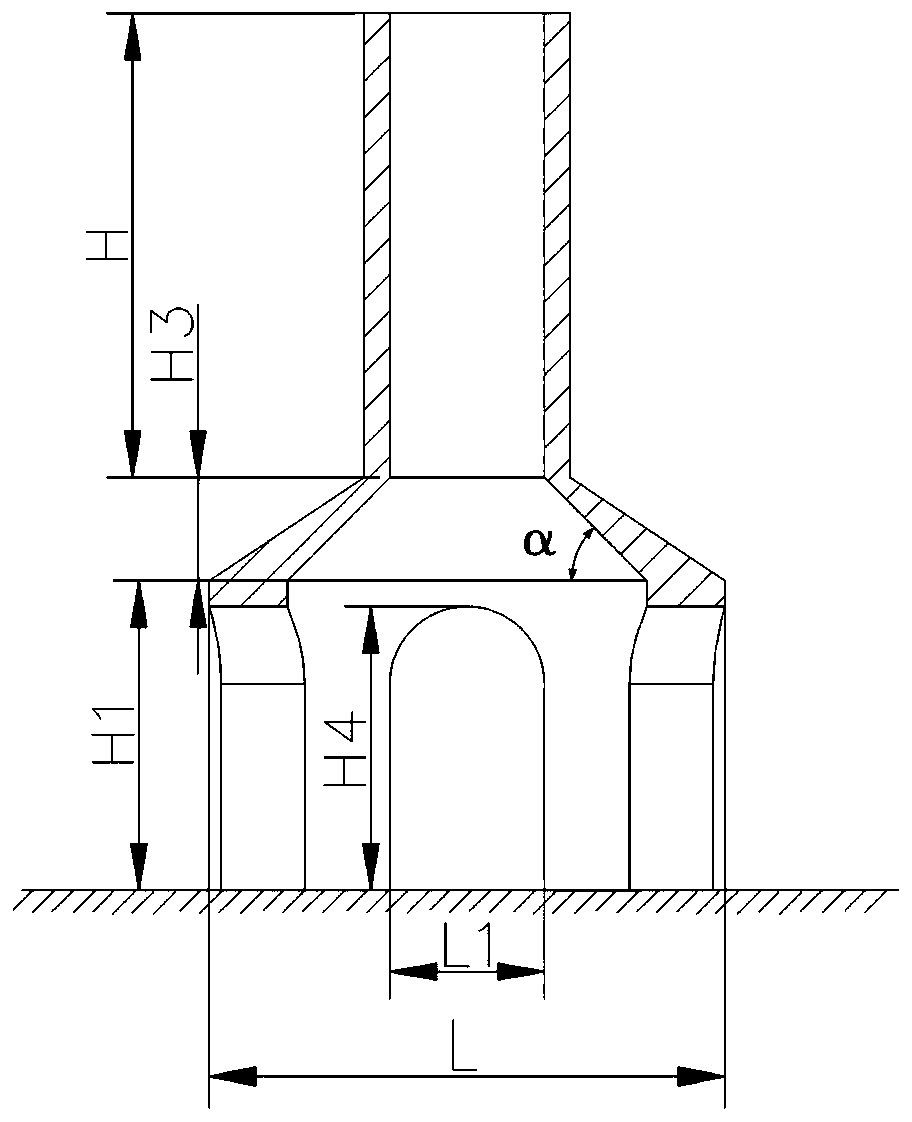
[0049] From the appearance structure, such as figure 1 It can be seen that the main body 1 includes two partial structures, an upper part and a lower part. Wherein, the upper part is a cylindrical structure; the lower part is a kiln-shaped structure, and at least three inverted U-shaped slots 3 are provided at symmetrical positions on the side walls of the lower part. The function of the crimping pin 2 here is that when the crimping pin 2 moves from the upper opening to the inside of the main body 1 , at least two wires 4 to be inlaid can be pressed against the upper inn...
Embodiment 2
[0064] Based on the aforementioned embodiment 1, in order to solve the technical problem that the crimping pin is easy to fall into the inside of the main body during the inlay operation and it is difficult to take it out, the crimping pin 2 has a pin head 5 to prevent it from slipping.
[0065] Figure 4 with Figure 5 The front view and cross-sectional view of a metallographic sample preparation mosaic tool provided by the embodiment of the present invention are respectively shown. It can be seen that the crimping pin 2 has a pin head 5 that is larger than the inner diameter of the opening on the main body of the tooling, so that the crimping pin 2 is When reaching the deepest position, the pin head 5 is stuck to the upper opening of the main body 1, so that it will not fall into the inside of the main body 1.
[0066] It should be noted here that the diameter of the pin head 5 is not only larger than the inner diameter of the upper opening of the main body 1, but also smal...
Embodiment 3
[0068] Based on the foregoing embodiments, in order to further improve the fixing effect of the wire material 4 to be inlaid, as Image 6 As shown, in a practicable manner, the crimping pin 2 has several crimping grooves 6 at axially symmetrical positions of the pin body. Figure 7 shows the use of Image 6 The crimping pin 2 shown is the front view of the tooling for fastening the wire 4 to be inlaid (filling the shaded part). It can be seen that based on the crimping groove 6 of the crimping pin 2, the wire 4 to be inlaid can be inserted into the crimping The groove 6 effectively ensures the verticality of the wire 4 to be inlaid when it is put into the main body 1 .
[0069] Preferably, the positions of the crimping grooves 6 on the crimping pins 2 are symmetrical, so as to ensure uniform stress on each wire 4 to be inlaid when fastened.
[0070] It should be noted that, in the embodiment of the present invention, the groove depth of the crimping groove 6 is less than or ...
PUM
 Abstract
Description
Claims
Application Information
 - R&D
- Intellectual Property
- Life Sciences
- Materials
- Tech Scout
- Unparalleled Data Quality
- Higher Quality Content
- 60% Fewer Hallucinations
Browse by: Latest US Patents, China's latest patents, Technical Efficacy Thesaurus, Application Domain, Technology Topic, Popular Technical Reports.
© 2025 PatSnap. All rights reserved.Legal|Privacy policy|Modern Slavery Act Transparency Statement|Sitemap|About US| Contact US: help@patsnap.com


