
A cold mounting tool and method for multiple fiber monofilaments

A cold inlay and fiber technology, applied in the field of materials, can solve the problems of multiple monofilament impact, fiber monofilament breakage, difficult positioning, etc., and achieve the effect of ensuring accuracy, small fiber damage, and wide application range.

Active Publication Date: 2021-07-20
NANJING UNIV OF AERONAUTICS & ASTRONAUTICS
View PDF6 Cites 0 Cited by
  • Summary
  • Abstract
  • Description
  • Claims
  • Application Information

AI Technical Summary

Problems solved by technology

3) Due to the small size, positioning is difficult, and when pouring into the cold mounting mold, it will impact multiple monofilaments and disrupt the original arrangement
Because the fiber needs to be stressed to keep it in a vertical state during fixing, it is likely that the brittle fiber monofilaments will be torn off, resulting in failure of the inlay

Method used


Image

  • A cold mounting tool and method for multiple fiber monofilaments
  • A cold mounting tool and method for multiple fiber monofilaments
  • A cold mounting tool and method for multiple fiber monofilaments

Examples


Embodiment 1

[0038] This embodiment provides a cold setting tool for multiple fiber monofilaments and a cold setting method using the cold setting tool.

[0039] Cold mounting tools include V-groove fiber parallel mounts and multi-antenna supports.

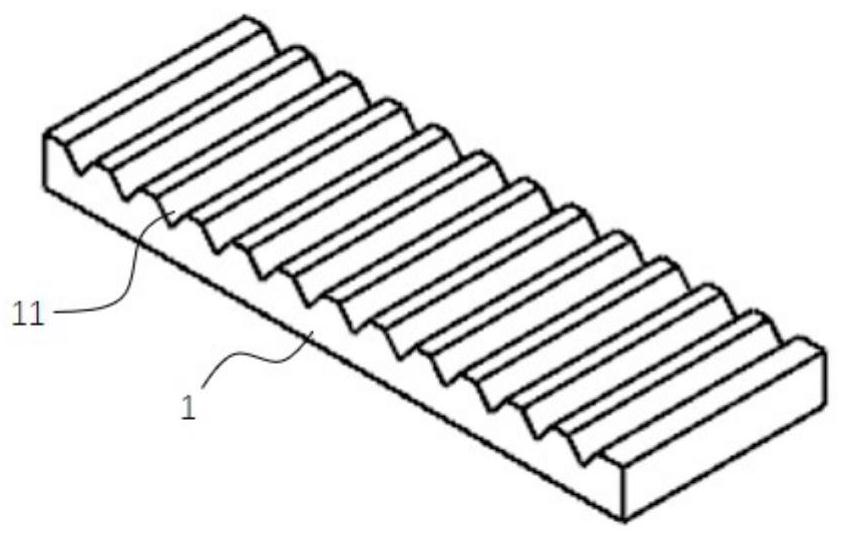
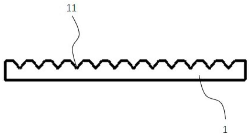
[0040] Such as Figure 1a with 1b As shown, the V-shaped groove fiber parallel seat 1 is a rectangular plate body with several V-shaped grooves 11 on the upper surface. The V-shaped grooves 11 are strip-shaped, arranged along the width direction of the rectangular plate body, extending from one side of the rectangular plate body to the other side, and several V-shaped grooves 11 are parallel to each other. The groove section of the V-shaped groove 11 is V-shaped, and can accommodate fiber monofilaments (non-lengthwise direction) in the plane direction of the groove section.

[0041] The V-groove fiber parallel seat 1 is made of a bendable material, specifically, a resin material.

[0042] Bend the V-shaped groove fiber parallel seat 1 so th...

Embodiment 2

[0067] This embodiment provides a cold setting tool for multiple fiber monofilaments and a cold setting method using the cold setting tool. Wherein, the structure of the cold mounting tool is the same as that of Example 1; in the cold mounting method for multiple fiber monofilaments, the multiple fiber monofilaments are multiple different fiber monofilaments in the fiber bundle. The method includes the following steps:

[0068] Step 1, preparing fiber monofilaments, including the following specific steps:

[0069] S1. Soak the fiber bundle in an organic solvent, sonicate and heat at the same time.

[0070] Specifically, put SiC fiber bundles with a length of 15 cm into a beaker with a diameter of 77 cm, a height of 107 cm, and a cup mouth diameter of 85 cm, and pour absolute ethanol until the fiber bundles are covered; pour clean water into an ultrasonic cleaner and heat to 35°C, put the beaker into a washing machine, the capacity of the ultrasonic washing machine is 3.2 lit...


PUM

PropertyMeasurementUnit
thicknessaaaaaaaaaa

Abstract

The invention discloses a cold inlay tool and method for multi-fiber monofilaments, comprising a V-shaped groove fiber parallel seat and a multi-antenna support frame; the V-shaped groove fiber parallel seat is a rectangular plate with several V-shaped grooves on the upper surface body, the V-shaped groove is strip-shaped, extending from one side of the rectangular plate to the other side, and several V-shaped grooves are parallel to each other; the curved V-shaped groove fiber parallel seat can form a circular ring; the multi-antennary support frame has a hollow There are several tentacles on the outer wall of the bracket cylinder; the V-shaped groove fiber parallel seat bent into a circular ring matches the inner diameter of the bracket cylinder and can be placed in the bracket cylinder; the outer edge of the antennae of the multi-antenna bracket and The cold mounting mold is matched, and the multi-antennium bracket can be placed in the cold mounting mold, and the outer edges of the tentacles are all against the inner wall of the cold mounting mold; The heights of the brackets are all lower than those in the cold mounting mold. The invention has the advantages of high efficiency, high accuracy and the like.

Description

technical field [0001] The invention belongs to the field of materials, and relates to the preparation of a ceramic matrix composite material test sample, in particular to a cold inlay tool and method for multiple fiber monofilaments. Background technique [0002] Continuous fiber-reinforced ceramic matrix composites have excellent properties such as high specific modulus, corrosion resistance, high temperature resistance, and insensitivity to cracks, and are one of the ideal candidate materials for high-temperature components of aero-engines. Due to the uneven diameter size at different positions of the same fiber monofilament, which is similar to a wedge shape, the force distribution on the fiber surface is uneven during the tension process, and an obvious stress concentration effect is formed at the smaller diameter. Therefore, when the interface transfers the load between the fiber and the matrix, it makes the fiber prone to breakage. However, there are few reports on t...

Claims


Application Information

Patent Timeline
Patent Type & Authority Patents(China)
IPC IPC(8): G01N1/36G01N1/30
CPCG01N1/30G01N1/36
Inventor 宋迎东贾蕴发高希光于国强方光武张世榕张盛
Owner NANJING UNIV OF AERONAUTICS & ASTRONAUTICS
Learn More