Reinforcing structure and reinforcing method of old house

A technology for strengthening structures and houses, applied in building components, building structures, building maintenance, etc., can solve problems such as load-bearing performance reduction, wall damage and aging, house collapse, etc., and achieve the effect of increasing stability and improving stability

Inactive Publication Date: 2020-07-24
河北天昊建筑设计有限公司
8 Cites 3 Cited by

AI-Extracted Technical Summary

Problems solved by technology

[0004] The above-mentioned existing technical solutions have the following defects: the above-mentioned wall will be damaged and aged after a long time, the loa...

Method used

As shown in Figure 3 and Figure 5, vertical stiffener 3 is provided with the draw-in groove 31 that inserts for transverse stiffener 4 away from the side wall of body of wall 1, and the depth of draw-in groove 31 is equal to the thickness of transverse stiffener 4, The draw-in slot 31 is provided with a through hole 42 near the inner wall of the body of wall 1, the side wall of the vertical reinforcing plate 3 away from the body of wall 1 is provided with a threaded hole 32 communicating with the through hole 42, and the side wall of the horizontal reinforcing plate 4 is far away from the body of wall 1. There are a number of accommodation grooves 43, the number of accommodation grooves 43 is equal to the number of card slots 31, the accommodation grooves 43 are provided with fixing bolts 41, the fixing bolts 41 pass through the through holes 42 and are screwed into the threaded holes 32, and the fixing bolts 41 do not protrude from the accommodation grooves 43 openings, the wall 1 is vertically provided with four decorative panels 6, and the decorative panels 6 are respectively fixed and bonded to the horizontal reinforcing panels 4 and vertical reinforcing panels 3 on the same side; the slot 31 can effectively prevent the horizontal reinforcing panels 4 from producing vertical The displacement in the vertical direction, the fixed bolt 41 will fix the horizontal reinforcement plate 4 and the vertical reinforcement plate 3, and increase the reinforcement effect of the vertical reinforcement plate 3 on the wall body 1. At the same time, the decorative plate 6 can make the interior more beautiful. The side wall of the horizontal reinforcement plate 4 is flush with the side wall of the vertical reinforcement plate 3, and the setting of the receiving groove 43 makes the fixing bolt 41 not protrude from the side wall of the horizontal reinforcement plate 4, which ensures that the decorative plate 6 can be connected with the side wall of the horizontal reinforceme...

Abstract

The invention relates to a reinforcing structure and a reinforcing method of an old house, and belongs to the technical field of house reinforcement. A plurality of vertical reinforcing plates abut against the inner side wall and the outer side wall of a wall body in parallel, a plurality of fixing nails are inserted between the vertical reinforcing plates and the wall body, a plurality of inserting holes are formed in the side walls, far away from the wall body, of the vertical reinforcing plates, a plurality of transverse reinforcing plates abut against the side walls, away from the wall body, of the vertical reinforcing plates in parallel, fixing bolts are arranged between the transverse reinforcing plates and the vertical reinforcing plates, a plurality of adjusting threaded sleeves are arranged on the inner side of the wall body, two sections of forward and reverse threads opposite in rotating direction are horizontally arranged on the inner walls of the adjusting threaded sleeves, two supporting threaded pipes opposite in thread direction are in threaded connection into the adjusting threaded sleeves, and the ends, away from the adjusting threaded sleeves, of the two supporting threaded pipes abut against the vertical reinforcing plates opposite to the inner side of the wall body. The reinforcing structure and the reinforcing method have the effects of improving the bearing performance of the wall body and ensuring the safety of the house.

Application Domain

Building repairsBuilding insulations

Technology Topic

Threaded pipeArchitectural engineering +2

Image

  • Reinforcing structure and reinforcing method of old house
  • Reinforcing structure and reinforcing method of old house
  • Reinforcing structure and reinforcing method of old house

Examples

  • Experimental program(2)

Example Embodiment

[0050] Example 1
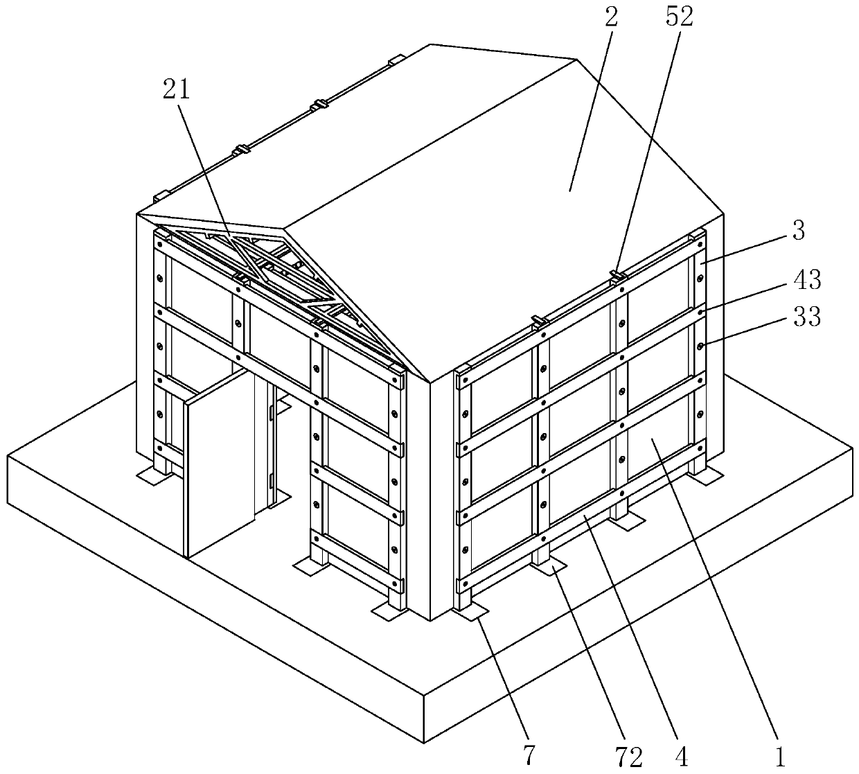
[0051] Reference figure 1 with figure 2 , Is the reinforcement structure of the old house disclosed in the present invention. The roof 2 is fixed above the four-sided wall 1, and the inner and outer side walls of the four-sided vertical wall 1 are parallel and abutted with a number of vertical reinforcing plates 3. In this embodiment There are four equally spaced vertical reinforcing plates 3 on the inside and outside of the same wall 1, and the vertical reinforcing plates 3 are opposite to each other inside and outside the wall 1, and the upper surface of the vertical reinforcing plate 3 is flush with the upper surface of the wall 1. The side walls of the vertical reinforcing plate 3 away from the wall 1 are horizontally fixed with a number of horizontal reinforcing plates 4. In this embodiment, the four vertical reinforcing plates 3 on the same side are fixed to four equally spaced horizontal reinforcing plates 4. Both the plate 3 and the horizontal reinforcement plate 4 are steel plates.
[0052] Such as image 3 As shown, an adjustment screw sleeve 5 is horizontally arranged between the vertical reinforcement plates 3 on the inner side of the opposite wall 1. In this embodiment, there are two parallel adjustment screw sleeves 5 between each pair of opposed walls 1. The adjustment screw sleeve 5 The inner wall is provided with two sections of positive and negative threads in opposite directions. The inner thread of the same adjusting screw sleeve 5 is connected with two oppositely threaded support solenoids 51. The two support solenoids 51 are far away from the end of the adjusting screw sleeve 5 and opposite to each other. The vertical reinforcement plate 3 on the inner side of the wall 1 is pressed tightly, the adjusting screw sleeve 5 and the supporting solenoid 51 are close to the top of the wall 1, and the top of each adjusting screw sleeve 5 is fixedly connected with two connecting plates 52, the top of the connecting plate 52 After extending to the top of the vertical reinforcement plate 3 located on the inner side of the wall 1, continue to extend through the roof 2 and then be fixedly connected to the vertical reinforcement plate 3 located on the outer side of the wall 1. A bracket is provided between the roof 2 and the connecting plate 52 21. The top end of the bracket 21 is fixedly connected to the inner wall of the roof 2, and the bottom end of the bracket 21 is fixedly connected to the upper surface of the connecting plate 52, so that the structure of the bracket 21, the connecting plate 52, the adjusting screw sleeve 5, the vertical reinforcement plate 3 and other structures are integrated and can be shared by each other The force greatly improves the stability of the reinforced structure.
[0053] Such as Figure 4 with Figure 5 As shown, the side wall of the vertical reinforcement plate 3 away from the wall 1 is prefabricated with a plurality of leveling grooves 33. In this embodiment, each vertical reinforcement plate 3 has three leveling grooves 33 on the side wall, and they are located on the two horizontal reinforcement plates 4 respectively. Between the vertical positions, the leveling groove 33 is near the side wall of the wall 1 with a hole 34, and a fixing nail 35 is inserted into the hole 34. The fixing nail 35 penetrates the hole 34 and then is nailed into the wall 1. The side wall of the nail cap of 35 away from the wall 1 is flush with the opening of the leveling groove 33, the side wall of the fixing nail 35 away from the wall 1 is provided with an injection hole 351, and the fixing nail 35 is inserted into a part of the side wall of the wall 1 There are a number of bonding holes 352 communicating with the glue hole 351. The side wall of the same glue hole 351 communicates with four bonding holes 352, and the bonding holes 352 are symmetrical in the longitudinal direction of the glue hole 351; 35 can fix the vertical reinforcing plate 3 on the side wall of the wall 1. After the fixing nail 35 is tightened, the construction glue is poured from the opening of the glue injection hole 351, so that the construction glue flows into the fixing nail 35 and the wall through the bonding hole 352 In the gap between the bodies 1, the effect of making the vertical reinforcement plate 3 more stable on the side wall of the wall 1 is achieved.
[0054] Such as image 3 with Figure 5 As shown, the side wall of the vertical reinforcement plate 3 away from the wall 1 is provided with a card slot 31 for the horizontal reinforcement plate 4 to be inserted. The depth of the card slot 31 is equal to the thickness of the horizontal reinforcement plate 4, and the card slot 31 is close to the inner wall of the wall 1. A through hole 42 is provided. The side wall of the vertical reinforcement plate 3 away from the wall 1 is provided with a threaded hole 32 communicating with the through hole 42. The side wall of the horizontal reinforcement plate 4 away from the wall 1 is provided with a plurality of receiving grooves 43. The number of fixing bolts 41 is equal to the number of card slots 31. The fixing bolts 41 are provided in the receiving groove 43. The fixing bolts 41 penetrate through the through holes 42 and screw into the threaded holes 32. The fixing bolts 41 do not protrude from the opening of the receiving groove 43. The four-sided decorative board 6 is arranged straight, and the decorative board 6 is fixed and bonded to the horizontal reinforcement board 4 and the vertical reinforcement board 3 on the same side respectively; the card slot 31 can effectively prevent the horizontal reinforcement board 4 from generating vertical displacement, and the fixing bolt 41 will The horizontal reinforcing plate 4 is fixedly connected with the vertical reinforcing plate 3 to increase the reinforcing effect of the vertical reinforcing plate 3 on the wall 1. At the same time, the decorative plate 6 can make the interior more beautiful. The arrangement of the slot 31 makes the side wall of the horizontal reinforcing plate 4 and the vertical The side walls of the reinforcing plate 3 are flush, and the accommodating groove 43 is arranged so that the fixing bolts 41 do not protrude from the side walls of the horizontal reinforcing plate 4, ensuring that the decorative plate 6 can have the largest contact area with the horizontal reinforcing plate 4 and the vertical reinforcing plate 3. In addition, the decorative board 6 is parallel to the side wall of the wall 1 to ensure the stability and aesthetics of the decorative board 6 after installation.
[0055] Such as image 3 As shown, the ground on both sides of the bottom end of the wall 1 is dug with a number of insertion holes 7 for the bottom end of the vertical reinforcement plate 3 to be inserted. The bottom end of the vertical reinforcement plate 3 is prefabricated and fixed with a number of reinforcing steel bars 71 for reinforcement The reinforcing steel bars 71 are located inside the insertion pit 7, and the reinforcing steel bars 71 are arranged horizontally. There is a reinforcement gap between the reinforcing steel bars 71 and the inner wall of the insertion pit 7, and a concrete layer 72 is poured in the reinforcement gap. Before fixing the vertical reinforcement plate 3, first Put the bottom end of the vertical reinforcement plate 3 and the reinforcing steel bars 71 into the insertion hole 34, and then pour concrete into the insertion hole 7 to form a concrete layer 72, so that the vertical reinforcement plate 3 and the ground are more stable, and then The effect of improving the stability of the wall 1.
[0056] The implementation principle of this embodiment is: when the house is reinforced, the bottom end of the vertical reinforcement plate 3 and the reinforcing steel bars 71 are inserted into the insertion pit 7, and the vertical reinforcement plate 3 is kept parallel to the side wall of the wall 1, and the The fixing nail 35 penetrates the hole 34 and then is nailed into the wall 1, and then the glue injection hole 351 is filled with construction glue, so that the construction glue fills the gap between the fixing nail 35 and the wall 1 through the bonding hole 352. Then use concrete to fill the reinforcement gap in the insertion pit 7 to form a concrete layer 72. After the vertical reinforcement plates 3 are fixed respectively, the horizontal reinforcement plates 4 are inserted into the rows of card slots 31 to make the horizontal reinforcement The side wall of the plate 4 away from the wall 1 is flush with the side wall of the vertical reinforcement plate 3 away from the wall 1, and a fixing bolt 41 is used to penetrate the through hole 42 and screw into the threaded hole 32 to fix the horizontal reinforcement plate 4 and the vertical reinforcement plate 3 To connect, screw both ends of each adjusting screw sleeve 5 into the two supporting screws 51, and lift up the adjusting screw sleeve 5 so that the ends of the two supporting screws 51 away from the adjusting screw sleeve 5 are respectively close to the inner side of the opposite wall 1. For the vertical reinforcement plate 3, twist the adjusting screw sleeve 5 so that the two supporting solenoids 51 move away from each other until the two opposite vertical reinforcement plates 3 are tightened. After all the adjusting screw sleeves 5 and the supporting solenoids 51 are installed, Drill holes on the side walls of the roof 2, and weld every two connecting plates 52 to the top of the same adjusting screw sleeve 5. The tops of the connecting plates 52 are separated from each other and extend to the top of the vertical reinforcement plate 3 on the inner side of the wall 1. Continue It extends through the roof 2 until it is welded to the top of the vertical reinforcement plate 3 located outside the roof 2, and then the bracket 21 is welded between the roof 2 and the connecting plate 52, so that the top of the bracket 21 is fixed inside the roof 2, and the bottom end of the bracket 21 is connected to the connecting plate. 52 The upper surface is welded, and finally the four-sided decorative board 6 is fixed and bonded to the side walls of the horizontal reinforcement board 4 and the vertical reinforcement board 3 located on the inner side of the wall 1, and the above-mentioned series of structures are arranged to increase the load-bearing capacity of the wall 1. Performance to ensure the safety of the house.

Example Embodiment

[0057] Example 2
[0058] A method for strengthening old houses, including the following steps:
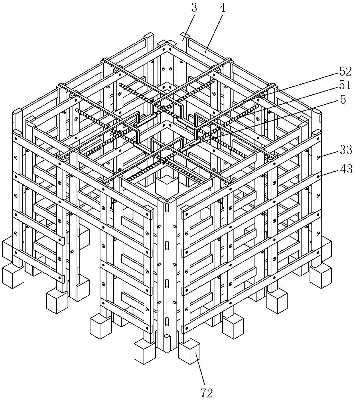
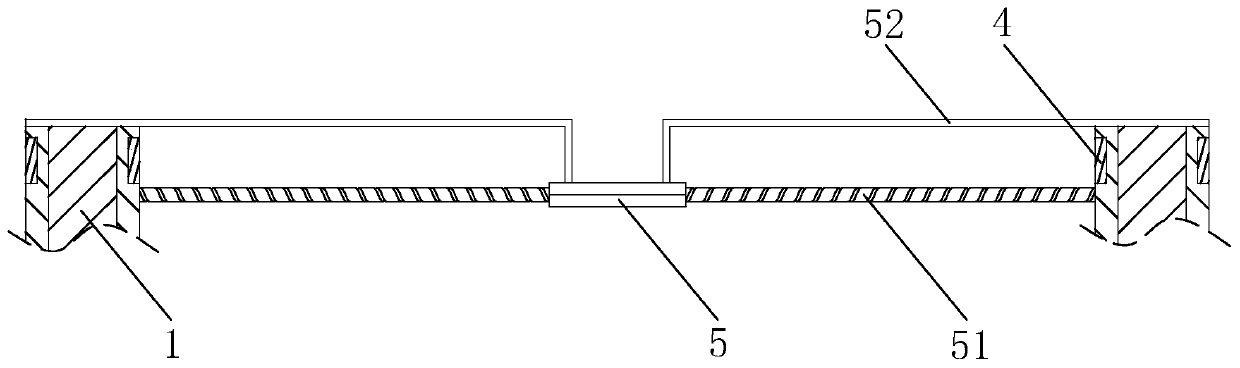
[0059] S1. Use factory-produced prefabricated vertical reinforcement plates 3, horizontal reinforcement plates 4 and adjusting screw sleeves 5, so that the bottom end of the vertical reinforcement plate 3 is provided with a number of reinforcement steel bars 71, and the vertical reinforcement plate 3 is far away from the side wall of the wall 1. The clamping groove 31, the leveling groove 33, the threaded hole 32 and the insertion hole 34, the horizontal reinforcing plate 4 is away from the vertical reinforcing plate 3 and a number of containing grooves 43 and through holes 42 are opened. The adjustment screw sleeve 5 is determined according to the length of the house to be reinforced Production length
[0060] S2. Dig a number of insertion holes 7 at the bottom end of the wall 1, put the bottom end of the vertical reinforcement plate 3 and a number of reinforcing steel bars 71 into the insertion holes 7, and keep the vertical reinforcement plate 3 parallel to the side walls of the wall 1 ,Put a number of fixing nails 35 through the socket 34 and then nail them into the wall 1;
[0061] S3. Fill the glue injection hole 351 with construction glue;
[0062] S4. Pour the space between the reinforcing steel bars 71 and the insertion pit 7 with concrete to form a concrete layer 72;
[0063] S5. Clip the horizontal reinforcing plate 4 into the card slot 31 so that the opening of the receiving groove 43 faces outward, and at the same time, the side wall of the horizontal reinforcing plate 4 away from the wall 1 is flush with the side wall of the vertical reinforcing plate 3 away from the wall 1. Pass the fixing bolt 41 through the through hole 42 and screw it into the threaded hole 32, so that the nut of the fixing bolt 41 is completely located in the receiving groove 43;
[0064] S6. Screw the two supporting solenoids 51 into the same adjusting screw sleeve 5 respectively, and lift up the adjusting screw sleeve 5 so that the outer ends of the two supporting solenoids 51 are close to the top of the wall 1, and screw the adjusting screw sleeve 5. So that the outer ends of the two supporting solenoids 51 are respectively pressed against the side walls of the vertical reinforcement plate 3 near the middle of the wall 1;
[0065] S7. One end of the connecting plate 52 is welded to the top wall of the screw sleeve, the top of the connecting plate 52 is extended to weld with the top of the vertical reinforcement plate 3 located inside the wall 1, and the inner wall of the roof 2 is perforated so that the top of the connecting plate 52 continues to extend to the roof 2 Externally, one end of the connecting plate 52 located outside the roof 2 is welded to the top end of the vertical reinforcement plate 3;
[0066] S8. Fix the top of the bracket 21 with the lower surface of the roof 2, and weld the bottom of the bracket 21 with the upper surface of the connecting plate 52;
[0067] S9. Fixing and bonding the decorative board 6 to the side wall of the vertical reinforcement board 3 located inside the wall 1, so that the upper surface of the decorative board 6 abuts against the supporting solenoid 51, and the lower surface of the decorative board 6 abuts against the ground.

PUM

no PUM

Description & Claims & Application Information

We can also present the details of the Description, Claims and Application information to help users get a comprehensive understanding of the technical details of the patent, such as background art, summary of invention, brief description of drawings, description of embodiments, and other original content. On the other hand, users can also determine the specific scope of protection of the technology through the list of claims; as well as understand the changes in the life cycle of the technology with the presentation of the patent timeline. Login to view more.

Similar technology patents

Parameter self-adaptive adjusting method and device

ActiveCN108342568AImprove accuracy and timelinessImprove stability
Owner:SHOUGANG JINGTANG IRON & STEEL CO LTD

Monitoring system based on J2EE framework and method

InactiveCN101847116AImprove stabilityspeed up development time
Owner:ZTE CORP

Gemcitabine hydrochloride lyophilized powder injection

ActiveCN101564381AImprove stabilityLow content of related substances
Owner:JIANGSU AOSAIKANG PHARMA CO LTD

Classification and recommendation of technical efficacy words

Why Eureka
Try Eureka