Axial chute type processing casing with back cavity for improving performance of gas compressor

A technology for processing casings and compressors, which is applied to machines/engines, components of pumping devices for elastic fluids, mechanical equipment, etc. Margin, effect of expanding stable operation range

Pending Publication Date: 2020-07-24
中船重工龙江广瀚燃气轮机有限公司
View PDF0 Cites 4 Cited by
  • Summary
  • Abstract
  • Description
  • Claims
  • Application Information

AI Technical Summary

Problems solved by technology

[0004] The purpose of the present invention is to solve the problem that the peak efficiency of the compressor is greatly reduced in the existing axial chute processing casing

Method used


Image

  • Axial chute type processing casing with back cavity for improving performance of gas compressor
  • Axial chute type processing casing with back cavity for improving performance of gas compressor
  • Axial chute type processing casing with back cavity for improving performance of gas compressor

Examples


specific Embodiment approach 1

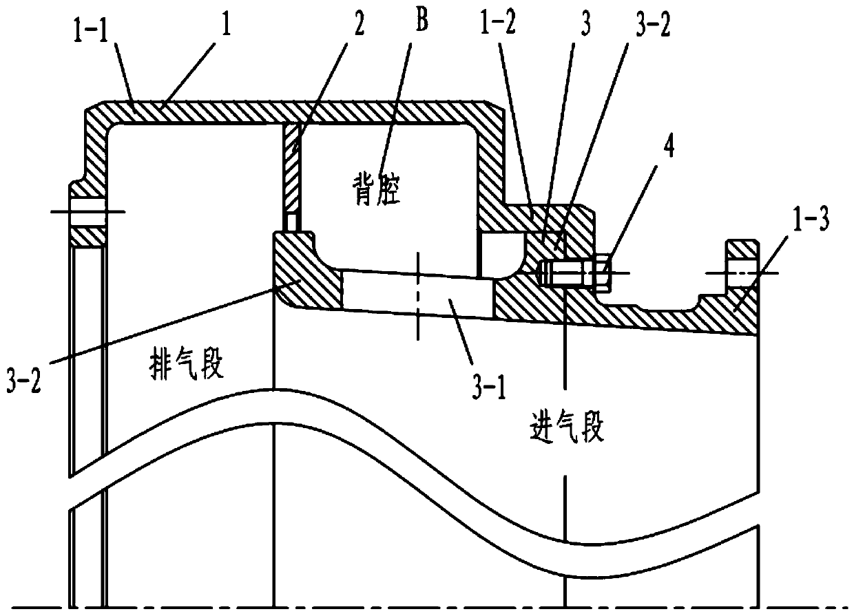
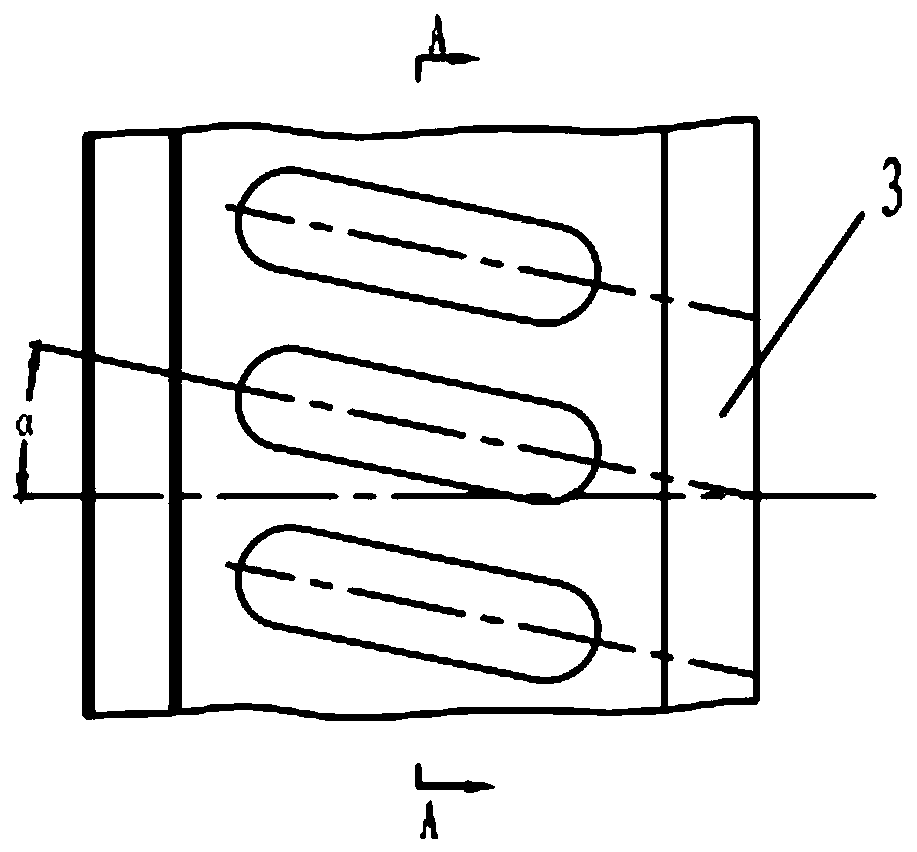
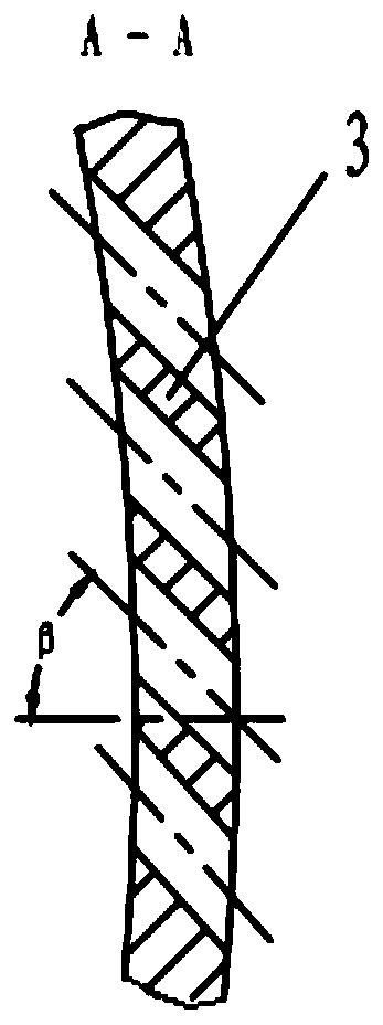
[0018] Specific implementation mode one: combine Figure 1 to Figure 3 Describe this embodiment, an axial chute processing casing with a back chamber for improving compressor performance in this embodiment includes an outer shell 1, an annular rib 2 and an axial chute 3, and the annular rib 2 is embedded in the outer shell 1, the axial chute 3 is installed in the inner hole of the annular rib 2 and the outer shell 1, and the axial chute 3 is provided with a plurality of slots 3-1 in the form of an annular array, and the slots 3-1 are respectively on the shaft Inclined upward and radially, the axial inclination angle of the slot 3-1 is α, α=10°~35°, the radial inclination angle of the slot 3-1 is β, β=30°~50°, the outer shell The space enclosed between 1 and the axial chute 3 is the back chamber B.

[0019] In this embodiment, the outer casing and the right side of the annular rib form an air intake section, and the outer casing and the left side of the annular rib form an exh...

specific Embodiment approach 2

[0020] Specific implementation mode two: combination figure 1 To illustrate this embodiment, the outer casing 1 of this embodiment includes a first ring segment 1-1, a second ring segment 1-2 and a third ring segment 1-3, the first ring segment 1-1, the second ring segment 1 -2 and the third ring segment 1-3 are coaxially arranged in sequence from left to right and made into one body. Such arrangement facilitates the installation of the annular rib and the axial chute, and also facilitates production. Other compositions and connections are the same as in the first embodiment.

specific Embodiment approach 3

[0021] Specific implementation mode three: combination figure 1 Referring to this embodiment, the inner diameters of the first ring segment 1-1, the second ring segment 1-2 and the third ring segment 1-3 in this embodiment decrease sequentially from left to right. Such arrangement facilitates a smooth transition with the inner diameter of the axial chute. Other compositions and connections are the same as those in Embodiment 1 or Embodiment 2.


PUM


Abstract

The invention relates to an axial chute type processing casing with a back cavity for improving the performance of a gas compressor, and relates to a casing. A problem that a peak efficiency of the gas compressor is excessively reduced in the existing axial chute type processing casing is solved. The axial chute type processing casing comprises an outer shell (1), an annular rib (2) and an axial chute (3), wherein the annular rib (2) is embedded into the outer shell (1), the axial chute (3) is arranged on an inner hole of the annular rib (2) and the outer shell (1), a plurality of slot holes (3-1) are formed in the axial chute (3) in an annular array manner, and are respectively inclined on an axial direction and a radial direction, wherein an axial inclination angle of each slot hole (3-1) is (alpha), and alpha is equal to 10-35 degrees, a radial inclination angle of each slot hole (3-1) is (beta), and the beta is equal to 30-50 degrees; and a space enclosed between the outer shell (1) and the axial chute (3) is a back cavity (B). And the axial chute type processing casing is used for improving performance of the gas compressor.

Description

technical field [0001] The invention relates to a casing. It specifically relates to a dynamic oil-gas separation device and belongs to the technical field of energy and power. Background technique [0002] The current gas turbine units have low surge margin under cruising conditions, poor anti-surge casing expansion effect of the prototype, large reduction in compressor efficiency under design conditions and low conditions, and complicated processing, which is not conducive to the high efficiency and high efficiency of this type of engine. Stable operation. Although the casing is treated with a conventional axial chute, the structure is simple, but the stability expansion effect is at a moderate level. When the return fluid re-enters the blade channel, the mixing loss is relatively large when it mixes with the mainstream fluid, resulting in a large decrease in the peak efficiency of the compressor. [0003] To sum up, the existing axial chute processing casing has the pro...

Claims


Application Information

Patent Timeline
Patent Type & Authority Applications(China)
IPC IPC(8): F04D29/40F04D29/66
CPCF04D29/403F04D29/667
Inventor 金鹏徐宁刘震张舟高思华
Owner 中船重工龙江广瀚燃气轮机有限公司
Why Eureka
Try Eureka