
Communication method, device and system

A communication method and optical signal technology, applied in the field of communication, can solve problems affecting the normal transmission of management services

Active Publication Date: 2020-07-24
HUAWEI TECH CO LTD
View PDF3 Cites 0 Cited by
  • Summary
  • Abstract
  • Description
  • Claims
  • Application Information

AI Technical Summary

Problems solved by technology

[0005]Since the management channel is established on the basis of the business channel, when the business channel is abnormal, it will affect the normal transmission of the management business

Method used


Image

  • Communication method, device and system
  • Communication method, device and system
  • Communication method, device and system

Examples


Embodiment Construction

[0033] The embodiments of the present application will be further described in detail below in conjunction with the accompanying drawings.

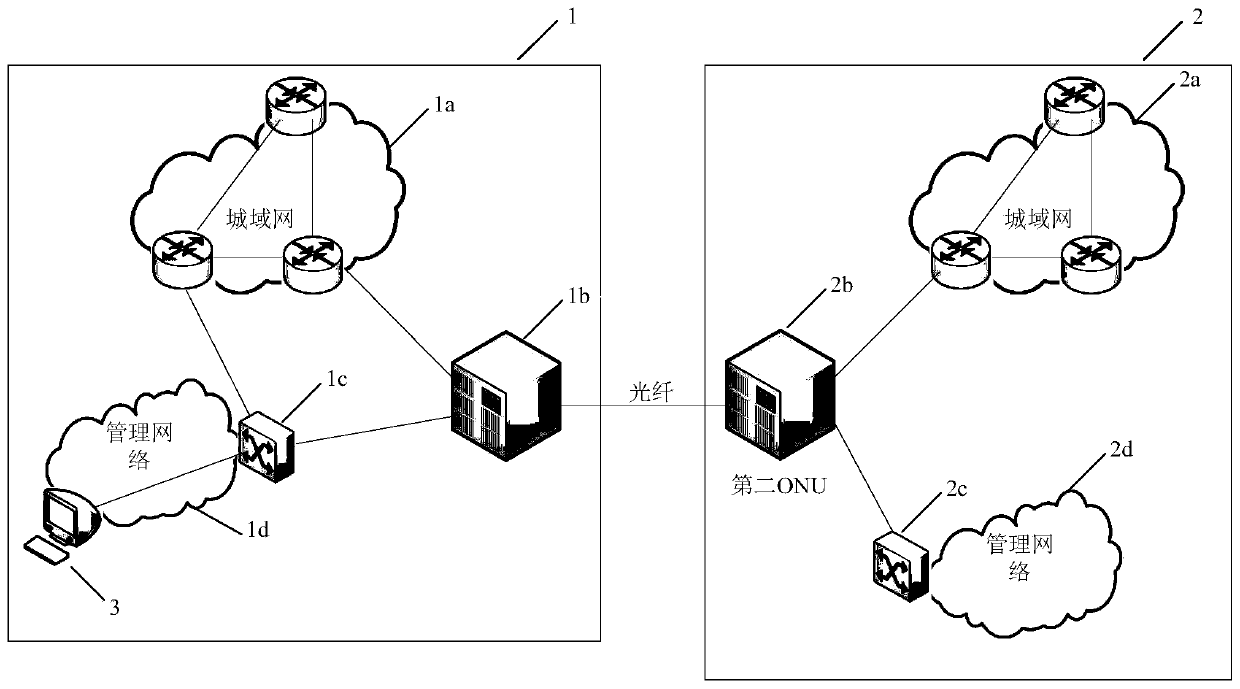
[0034] MANs and ONUs are deployed in different areas, which can be cities, etc. The metropolitan area network in each area is connected to the ONU, and the ONUs in each area are connected through optical fibers, so that the metropolitan area networks in different areas are interconnected. For example, see figure 1 , the metropolitan area network 1a deployed in area 1 is connected to the ONU1b deployed in area 1, the metropolitan area network 2a deployed in area 2 is connected to the ONU2b deployed in area 2, and the ONU1b and ONU2b are connected through optical fibers.

[0035] A machine room can be deployed in the area, and the equipment in the machine room belongs to a local area network, which is connected to the MAN deployed in the area where the machine room is located.

[0036] still see figure 1 ,by figure 1 Take area 1 in as a...


PUM


Abstract

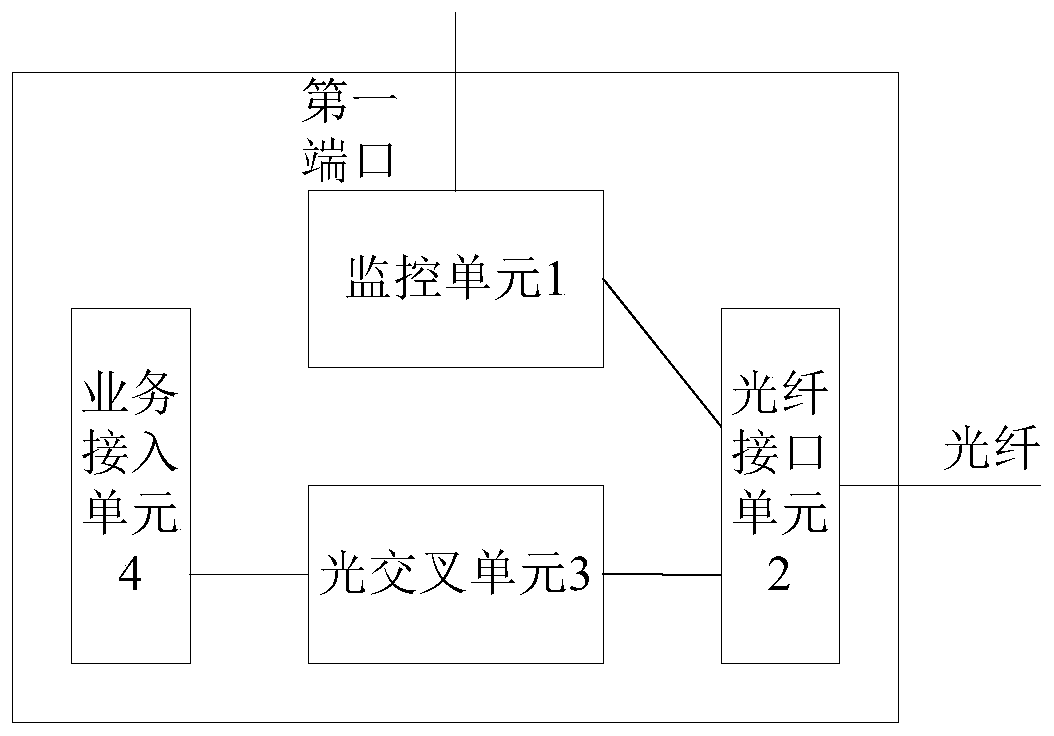
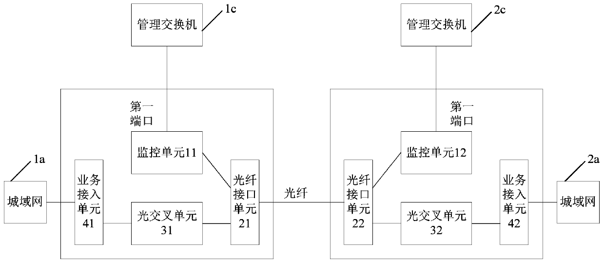
The invention discloses a communication method, device and system, and belongs to the field of communication. The method comprises the steps that: a first optical network node (ONU) receives a management message from a management network through a first port included in the first ONU and receives a service message from a metropolitan area network through a second port included in the first ONU, the management message belonging to a management service, and the service message belonging to a user service; the first ONU generates a data frame, wherein the data frame comprises message data in themanagement message; the first ONU converts the data frame into a first optical signal with a first wavelength and converts the service message into a second optical signal with a second wavelength, wherein the first wavelength is different from the second wavelength; and the first ONU sends the first optical signal and the second optical signal to a second ONU. The normal transmission of the management service can be prevented from being influenced.

Description

technical field [0001] The present application relates to the communication field, in particular to a communication method, device and system. Background technique [0002] A metropolitan area network and an optical network node (optical network unit, ONU) are deployed in different areas, and the area may be a city or the like. The MAN in each area is connected to the ONU, and the ONUs in each area are connected through optical fibers. A machine room can be deployed in the area, and the devices in the machine room form a local area network, which is connected to the MAN deployed in the area where the machine room is located. The equipment in the equipment room is connected to the management switch to form a management network of the equipment room, through which the equipment in the equipment room can be managed. [0003] For the LANs in two areas, a service channel can be established between the LANs in the two areas. The service channel includes the channel between the L...

Claims


Application Information

Patent Timeline
Patent Type & Authority Applications(China)
IPC IPC(8): H04J14/02H04L12/46H04L12/861
CPCH04J14/0239H04J14/0267H04J14/0272H04L12/4645H04L49/9042H04L12/46
Inventor 杨涛李金高宋利钱卫京郑春阳
Owner HUAWEI TECH CO LTD
Learn More