Computer control and monitoring combined device

A combined device and computer technology, which is applied in the direction of supporting machines, mechanical equipment, machine platforms/supports, etc., can solve the problems of inability to take clear pictures in edge areas, cannot meet the needs of use, and is inconvenient to use, so as to improve automatic adjustment And the effects of controlling performance, ensuring stability, and avoiding dead ends

Inactive Publication Date: 2020-07-24
YANTAI UNIV
View PDF0 Cites 5 Cited by
  • Summary
  • Abstract
  • Description
  • Claims
  • Application Information

AI Technical Summary

Problems solved by technology

[0003] Computer monitoring systems generally use liquid crystal displays with camera shooting functions as monitoring devices. For users, cameras are fixedly installed in a certain position, resulting in the inability to take clear pictures in the edge area, thus forming a monitoring dead zone. Corresponding adjustments are made according to the needs of use, which is very inconvenient to use and cannot meet the needs of use

Method used


Image

  • Computer control and monitoring combined device
  • Computer control and monitoring combined device
  • Computer control and monitoring combined device

Examples


Embodiment Construction

[0022] The following will clearly and completely describe the technical solutions in the embodiments of the present invention with reference to the accompanying drawings in the embodiments of the present invention. Obviously, the described embodiments are only some, not all, embodiments of the present invention. Based on the embodiments of the present invention, all other embodiments obtained by persons of ordinary skill in the art without making creative efforts belong to the protection scope of the present invention.

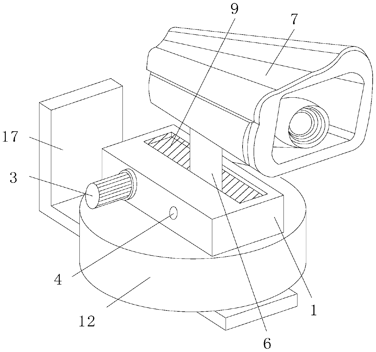
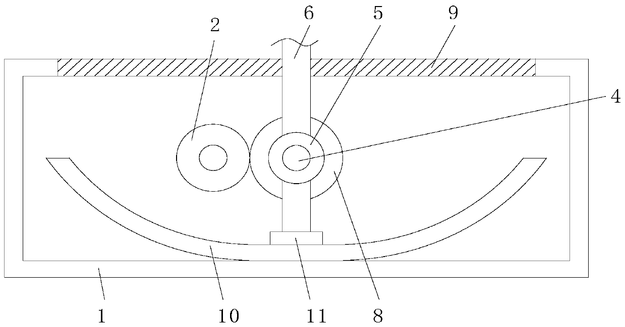
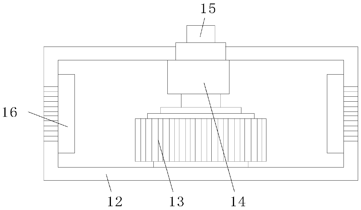
[0023] see Figure 1-3 , the present invention provides a technical solution: a computer-controlled monitoring combination device, including an installation box 1, a driving gear 2, a reduction motor 3, a main shaft 4, a fixed sleeve 5, a connecting rod 6, a camera 7, a driving gear 8, and a track 10. Slider 11, base box 12, driving motor 13, reducer 14, transmission rod 15, radiator 16 and installation frame 17, the driving gear 2 is installed on the left sid...


PUM


Abstract

The invention relates to the technical field of monitoring facilities. The invention relates to a computer, in particular to a computer-controlled monitoring combination device. The device comprises amounting box, a driving gear, a gear motor, a main shaft, a fixing sleeve, a connecting rod, a camera, a driving gear, a rail, a sliding block, a base box, a driving motor, a speed reducer, a transmission rod, a radiator and a mounting frame, the driving gear is mounted on the left side of the front-rear middle of the inner wall of the mounting box through a round rod, one side of the gear motoris fixedly connected with one side of the mounting box, the output end of the gear motor is in transmission connection with one end of the round rod on the driving gear, and two ends of the spindle are rotatably connected with the front-rear middle of the inner wall of the mounting box. The purpose that the camera can be freely adjusted at any angle of 180 degrees in the vertical plane angle is achieved, the automatic adjustment and controllable performance of the camera can be improved, a monitoring dead zone is avoided, the monitoring area is wider, and the use requirement of a monitoring system is met.

Description

technical field [0001] The invention relates to the technical field of monitoring facilities, in particular to a computer-controlled monitoring combination device. Background technique [0002] The monitoring system is mainly composed of two parts: front-end equipment and back-end equipment. Perform their duties and establish corresponding links with various devices in the central control system through wired, wireless or optical fiber transmission media. [0003] Computer monitoring systems generally use liquid crystal displays with camera shooting functions as monitoring devices. For users, cameras are fixedly installed in a certain position, resulting in the inability to take clear pictures in the edge area, thus forming a monitoring dead zone. Corresponding adjustments are made according to the usage requirements, which is very inconvenient to use and cannot meet the usage requirements. Contents of the invention [0004] (1) Solved technical problems [0005] In vie...

Claims


Application Information

Patent Timeline
Patent Type & Authority Applications(China)
IPC IPC(8): H04N5/225F16M11/12
CPCF16M11/12H04N23/50
Inventor 潘庆先
Owner YANTAI UNIV
Why Eureka
Try Eureka