Laser light source unit, illumination apparatus and method for generating laser light

A technology of laser light source and lighting equipment, which is applied in the field of lighting equipment and laser generation

Pending Publication Date: 2020-07-24
HELLA KGAA HUECK & CO
View PDF5 Cites 0 Cited by
  • Summary
  • Abstract
  • Description
  • Claims
  • Application Information

AI Technical Summary

Problems solved by technology

Thus, a change or alteration of th

Method used


Image

  • Laser light source unit, illumination apparatus and method for generating laser light
  • Laser light source unit, illumination apparatus and method for generating laser light
  • Laser light source unit, illumination apparatus and method for generating laser light

Examples


Example Embodiment

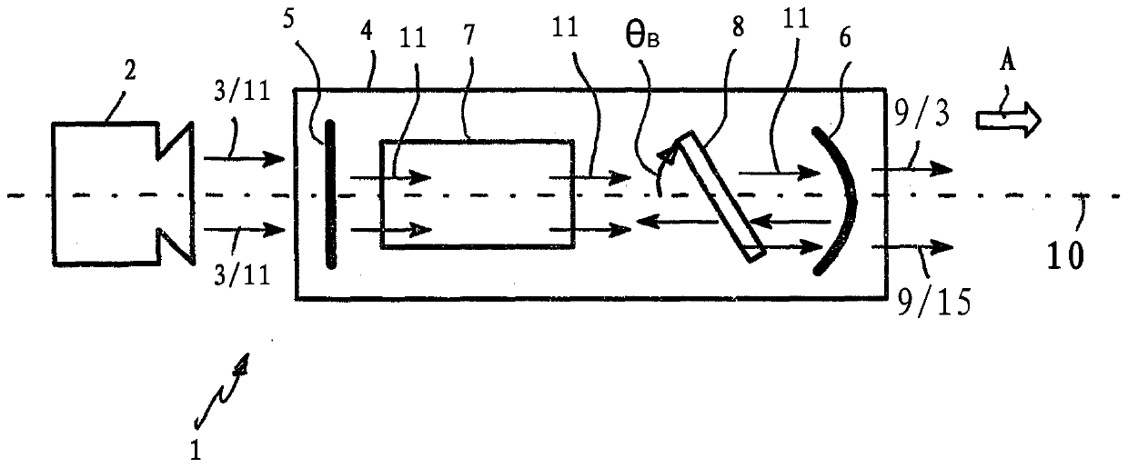
[0021] The laser light source unit 1 according to the present invention can be used in a lighting device (for example, a headlight) for a vehicle, or used as an interior lighting device in a vehicle, for example. Alternatively, the laser light source unit 1 may also be used in other light sources for other purposes.

[0022] The laser light source unit 1 basically includes a pump device 2 for generating a pump beam 3 and a resonator 4. The resonator 4 has a first end mirror 5 on the side facing the pumping device 2 and a second end mirror 6 on the side facing away from the pumping device 2. An activated laser medium 7 and a birefringent medium 8 are arranged between the first end mirror 5 and the second end mirror 6 of the resonator 4. In this embodiment, the activated laser medium 7 is arranged between the first end mirror 5 and the birefringent medium 8. The birefringent medium 8 is arranged between the activated laser medium 7 and the second end mirror 6.

[0023] The first e...


PUM


Abstract

A laser light source unit for vehicles has a resonator (4) containing a first end mirror (5) and a second end mirror (6), between which an active laser medium (7) is arranged, and having a pump device(2) for generating pump radiation (3) which can be introduced into the resonator (4) via the first end mirror (5), wherein a rotatable birefringent medium (8) is arranged in the resonator (4) in sucha way that, according to a rotational position of the birefringent medium (8), a preferred radiation (15) having different wavelengths (12, 13, 14) is stimulated in the active laser medium (7). Pr:YLF is used in particular as the active medium. If the birefringent medium (8) turns continually, preferred radiation (15) having green (12), orange (13) and red (14) wavelengths can be generated in short time intervals such that, when the rotational speed is sufficiently high, a laser light (9) of white luminous colour is emitted by means of additive colour mixing with the pump radiation (3) havinga blue wavelength (11).

Description

technical field [0001] The present invention relates to a laser light source unit, especially a laser light source unit for lighting equipment of a vehicle, the laser light source unit has a resonator comprising a first end mirror and a second end mirror, between the first end mirror and the second end mirror The active laser medium is arranged between the two end mirrors and has a pumping device for generating a pump beam which can be introduced into the resonator via the first end mirror. [0002] The invention also relates to a lighting device for a vehicle. [0003] The invention also relates to a method for generating laser light according to the preamble of claim 9 . Background technique [0004] A laser light source unit for a vehicle is known from DE 10 2015 121 693 A1, which has a resonator comprising a first end mirror and a second end mirror, wherein a There is an active laser medium. The activated laser medium is subjected to a pump beam by means of a pump dev...

Claims


Application Information

Patent Timeline
IPC IPC(8): H01S3/08H01S3/106H01S3/16H01S3/06
CPCH01S3/08036H01S3/106H01S3/1613H01S3/061H01S3/0809H01S3/1653F21S41/16B60Q3/60H01S3/0604H01S3/08059H01S3/08086H01S3/09415
Inventor M·德鲁佩尔D·杜姆K·埃勒特B·费舍尔J·翰森M·卡普L·普尔特纳C·特布拉格B·维勒克J-H·威尔洛德特
Owner HELLA KGAA HUECK & CO
Why Eureka
Try Eureka