Flight control surface for aircraft, method for manufacturing flight control surface and aircraft

A technology for flight control surfaces and aircraft, applied in the field of flight control surfaces, can solve the problems of increasing weight and manufacturing time, and achieve the effects of saving weight, being less prone to breakage, and maintaining electrical continuity

Pending Publication Date: 2020-07-28
AIRBUS OPERATIONS SL
View PDF9 Cites 0 Cited by
  • Summary
  • Abstract
  • Description
  • Claims
  • Application Information

AI Technical Summary

Problems solved by technology

Furthermore, to perform the countersunk installation of said rivets, it is necessary to place a filler between the U-shaped metal profiles, thus increasing the weight and manufacturing time

Method used


Image

  • Flight control surface for aircraft, method for manufacturing flight control surface and aircraft
  • Flight control surface for aircraft, method for manufacturing flight control surface and aircraft
  • Flight control surface for aircraft, method for manufacturing flight control surface and aircraft

Examples


Embodiment Construction

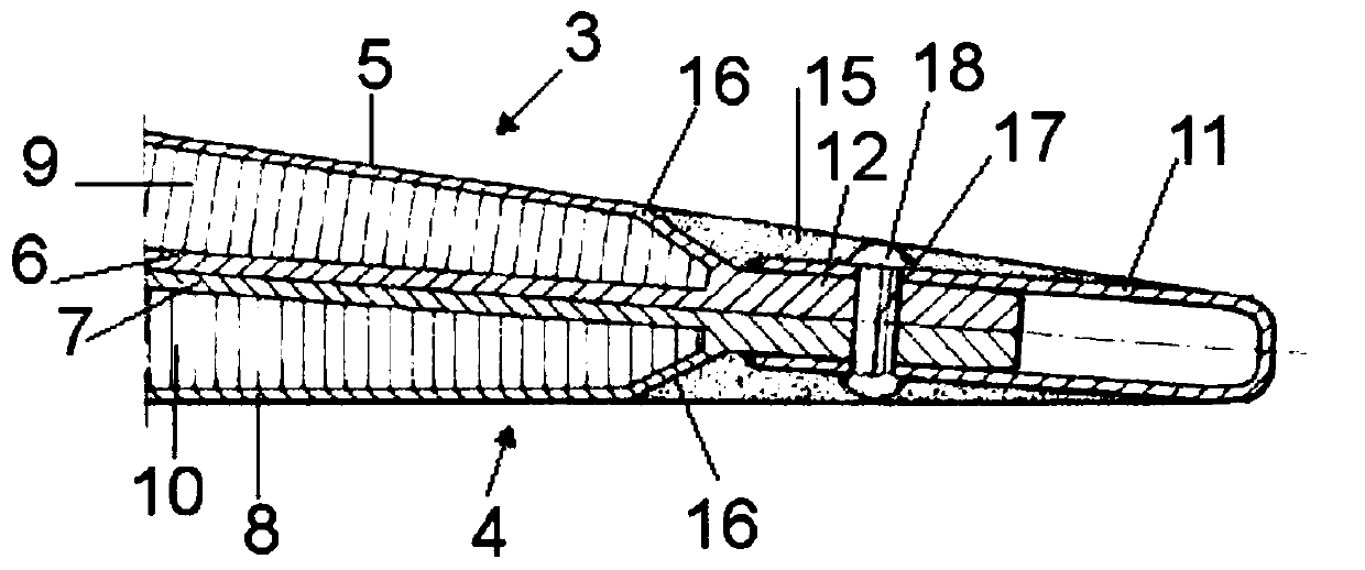
[0032] figure 1 A control surface according to the prior art is disclosed, wherein the body (1) is depicted as comprising an upper cover (3) and a lower cover (4), including an upper and a lower skin of each cover (3, 4) skins (5, 6, 7, 8), and upper and lower skins (5, 6, 7, 8) of each cover (3, 4) and core members (9, 10 ).

[0033] Furthermore, the skins (5, 6, 7, 8) of the covers (3, 4) comprise extensions (12) in their length which extend beyond the core member (9 , 10) Length. This extension (12) defines a stepped area (16) between areas of the main body (1) in which there are core members (9, 10) without core members in the extension (12) itself (9, 10).

[0034] figure 1 A U-shaped profile (11) enclosing an extension (12) of the main body (1) and a filler material (15) filling the gap between the stepped area (16) and the U-shaped profile (11) so as to achieve a smooth transition are disclosed . Another possibility known in the prior art would be to have U-shape...


PUM


Abstract

A flight control surface for an aircraft, a method for manufacturing the flight control surface and an aircraft are disclosed. The flight control surface comprises: a main body (1) comprising an upperand lower cover (3, 4), upper and lower skins (5, 6, 7, 8) and a core member (9, 10), a prolongation (12) of their length over the length of the core member defining a stepped area (16), a trailing edge (2) comprising a U-shaped profile (11) enclosing the prolongation, the U-shaped profile (11) extending towards the main body in the chordwise direction up to the stepped area (16) and comprising asection that progressively decreases, the trailing edge comprising a first and a second set of rivets (13, 14) located in the prolongation, the first set of rivets joining the upper and lower coversand the second set of rivets joining the U-shaped profile, the upper and lower covers.

Description

technical field [0001] The invention relates to a flight control surface of an aircraft, and also to a method of manufacturing the flight control surface. Background technique [0002] A control surface of an aircraft is known comprising an upper cover and a lower cover, wherein each cover comprises a sandwich carbon fiber structure having an upper skin and a lower skin, and between said upper skin and said lower skin core components. Furthermore, said skin comprises an extension in its length which exceeds the length of the core member in the chordwise direction of the control surface, thus in the region of the trailing edge due to the absence of the core at the edge of the control surface Generate steps. This step has a great influence on the drag caused by the aerodynamic surface. [0003] To avoid loss of aerodynamic drag, an epoxy filler was applied to smooth the aforementioned steps. Application of padding is time consuming and also adds weight to the flight contro...

Claims


Application Information

Patent Timeline
Patent Type & Authority Applications(China)
IPC IPC(8): B64C9/00B64C1/12
CPCB64C9/00B64C1/12B64C7/00B64C9/02B64F5/40Y02T50/40B29C65/60B29L2031/3076B64C3/26
Inventor 罗伯特·科比艾尔艾奇米格尔·安格尔·门德斯·罗德里格斯胡安·安东尼奥·桑切斯·鲁伊斯阿尔贝托·巴尔萨-冈萨雷斯
Owner AIRBUS OPERATIONS SL
Why Eureka
Try Eureka