Lifting device and AGV with device

A lifting device, trolley technology, applied in the direction of lifting device, lifting frame, etc., can solve the problems of short lead screw life, complex lifting and rotating structure design, lead screw plus cam and multi-link jacking cost, etc. The effect of installation and debugging difficulty and cost

Pending Publication Date: 2020-07-28
BEIJING JINGDONG QIANSHITECHNOLOGY CO LTD
View PDF14 Cites 2 Cited by
  • Summary
  • Abstract
  • Description
  • Claims
  • Application Information

AI Technical Summary

Problems solved by technology

Existing schemes can achieve the intended purpose, but each scheme has limitations of use and inherent defects
Especially there is currently no perfect structure for small handling AGVs
[0003] For the existing AGV trolley, due to its particularity, the center of the lifting and rotating structure is also the center of the entire car body. It is easy to cause the phenomenon of lifting stuck
Therefore, the design of the lifting and rotating structure is more complicated and difficult to realize
The existing solutions place the driving force around the center, such as the multi-screw structure, where three ball screws arranged at 120° are used to realize the lifting action. It is difficult to install and debug the force on the three screws at the same time. Lead screw life will be shorter
The flaw in the structure of the hollow lead screw is that the gears not only mesh but also move axially, and the wear is relatively large, which seriously affects the service life
The structure of the rotary lifting bucket is relatively poor in bearing partial load, and is not suitable for heavy-duty AGVs
Lead screw plus cam and multi-link jacking cost more and are also difficult to debug
Cylinders, oil cylinders, and electric cylinders are not suitable for small handling AGVs

Method used


Image

  • Lifting device and AGV with device
  • Lifting device and AGV with device
  • Lifting device and AGV with device

Examples


Embodiment approach

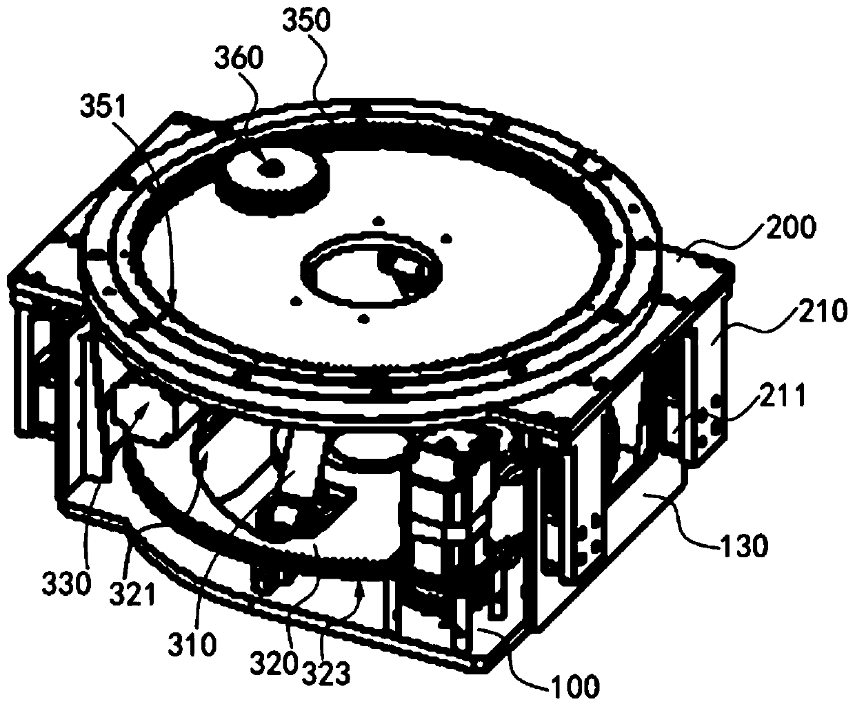
[0078] refer to figure 1 , which typically shows a perspective view when the lifting device proposed in the present disclosure is installed on an AGV trolley. In this exemplary embodiment, the lifting device proposed in the present disclosure is described as being applied to an AGV trolley as an example. Those skilled in the art can easily understand that in order to apply the relevant design of the present disclosure to other types of running gear or transportation equipment, various modifications, additions, substitutions, deletions or other modifications are made to the following specific embodiments variations, which remain within the scope of the principles of the lift proposed by the present disclosure.

[0079] Such as figure 1 As shown, in this embodiment, the lifting device proposed by the present disclosure can be installed between the fixed module and the lifting module, so that the lifting module can be arranged on the fixed module in a liftable manner. Wherein,...


PUM


Abstract

The disclosure provides a lifting device and an AGV with the device. The lifting device comprises at least one lifting connecting rod, a turntable and a lifting driving mechanism. The at least one lifting connecting rod is obliquely arranged relative to a fixing module, the lower ends of the lifting connecting rods are rotatably and slidably connected to the fixing module, and the upper ends of the lifting connecting rods are rotatably connected to a lifting module. The turntable is rotatably arranged between the fixing module and the lifting module, and the turntable is provided with at leastone hole through which the at least one lifting connecting rod penetrates. Each hole is configured in the mode that the hole wall on one side serves as a contact hole wall and abuts against the lowerend of the corresponding lifting connecting rod, and the orthographic projection of the contact hole wall on the turntable is in the Archimedes spiral shape. The lifting driving mechanism is in transmission connection with the turntable, and the lifting driving mechanism is configured to drive the turntable to rotate. The lifting device is configured to slide the lower ends of the lifting connecting rods by rotating the turntable, so that the lifting connecting rods drive the lifting module to ascend and descend relative to the fixing module.

Description

technical field [0001] The present disclosure relates to the technical field of logistics storage and transportation equipment, in particular to a lifting device and an AGV trolley equipped with the device. Background technique [0002] The lifting and rotating structure of the existing AGV trolley usually includes design schemes such as multi-lead screw, hollow lead screw, rotating bucket, lead screw plus cam, multi-link, cylinder, oil cylinder and electric cylinder. Existing schemes can achieve the intended purpose, but each scheme has usage limitations and inherent defects. Especially on the small handling AGV, there is no perfect structure at present. [0003] For the existing AGV trolley, due to its particularity, the center of the lifting and rotating structure is also the center of the entire car body. It is easy to cause the lifting jam phenomenon. Therefore, the design of the lifting and rotating structure is relatively complicated and difficult to realize. The ...

Claims


Application Information

Patent Timeline
Patent Type & Authority Applications(China)
IPC IPC(8): B66F7/06B66F7/28B66F9/065B66F9/075
CPCB66F7/0633B66F7/28B66F9/065B66F9/063B66F9/075
Inventor 张金虎
Owner BEIJING JINGDONG QIANSHITECHNOLOGY CO LTD
Why Eureka
Try Eureka