A Method for Determining the Inclination Angle of Each Circle of Fresnel Heliostat

The technology of heliostat and circle is applied in the field of solar energy utilization, which can solve the problems of poor condensing effect of flat mirror, difficulty in adjusting sub-mirrors, high cost, etc., so as to reduce the difficulty of installation and debugging, and realize the effect of condensing and good condensing light.

Active Publication Date: 2019-03-29
SOUTHEAST UNIV
View PDF7 Cites 0 Cited by
  • Summary
  • Abstract
  • Description
  • Claims
  • Application Information

AI Technical Summary

Problems solved by technology

The heliostat is composed of multiple sub-mirrors. If a spherical mirror is used for each sub-mirror, a single spherical heliostat can form a multiple light-gathering ratio, and a relatively high total light-gathering ratio can be achieved with a small number of units. However, the curvature of the spherical mirror There is a definite relationship between the radius and the distance from the center of the heliostat to the center of the heat-absorbing surface. Therefore, as long as the distance is different, the surface shape of the heliostat will be different. Correspondingly, there will be a variety of heliostats and sub-mirrors in a mirror field. specifications, the cost is high, and it is difficult to adjust the sub-mirror; if each sub-mirror uses a flat mirror, although the specification is uniform, the cost of manufacturing and debugging is low, but the light-gathering effect of the flat mirror is poor, and the same total light-gathering ratio can be achieved. The number of spherical heliostats is several times that of spherical heliostats, and the function of concentrating light cannot be well realized

Method used


Image

  • A Method for Determining the Inclination Angle of Each Circle of Fresnel Heliostat
  • A Method for Determining the Inclination Angle of Each Circle of Fresnel Heliostat
  • A Method for Determining the Inclination Angle of Each Circle of Fresnel Heliostat

Examples


Embodiment Construction

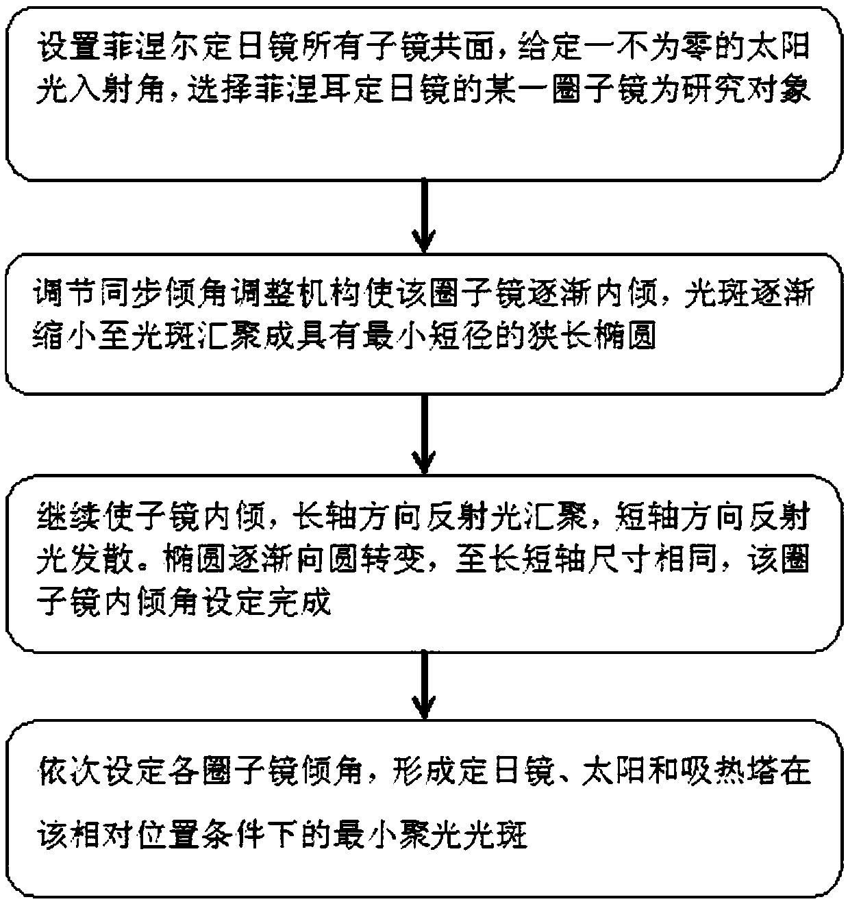
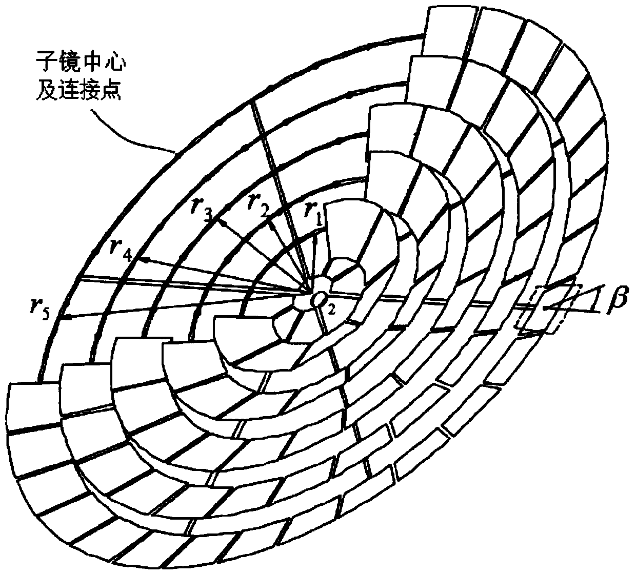
[0029] Such as figure 1 and 3 As shown, a method for determining the inclination angle of each circle of a Fresnel heliostat includes the following steps:

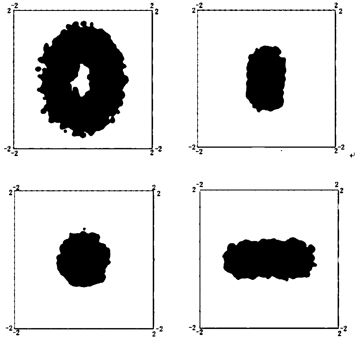
[0030] (1) Set all the sub-mirrors of the Fresnel heliostat to be coplanar, and given a non-zero incident angle of sunlight, select a certain circle mirror of the Fresnel heliostat, the circle mirror is in the absorption tower The spot on the hot surface is a larger hollow ellipse;

[0031] (2) The circle mirror is gradually tilted inward through the synchronous inclination adjustment mechanism, so that the light spot gradually shrinks until the light spot converges into a long and narrow ellipse with the smallest minor axis, and the reflected light in the direction of the minor axis converges to the extreme;

[0032] (3) Continue to tilt the sub-mirror inward, the reflected light in the direction of the major axis continues to converge, the light in the direction of the minor axis begins to diverge, and the ellipse begi...


PUM


Abstract

The invention discloses a method for determining dip angles of all rings of sub-mirrors of a Fresnel heliostat. The method includes the following steps that (1) all sub-mirrors of the Fresnel heliostat are set to be coplanar, a sunlight incidence angle which is not equal to zero is given, a certain ring of sub-mirrors of the Fresnel heliostat is selected, and light spots of the ring of sub-mirrors are a large hollow ellipse; (2) a synchronization dip angle adjusting mechanism is used for enabling the ring of sub-mirrors to be inclined inwards gradually, the light spots are gradually decreased until the light spots are gathered into a narrow ellipse with a minimum short shaft, and reflection light in the short shaft direction is gathered to be superlative; (3) the sub-mirrors are inclined inwards continuously, reflection light in the long shaft direction is continuously gathered, light in the short shaft direction starts to be scattered, the ellipse becomes to turn to a circle until the sizes of the long and short shafts are the same, and setting of the dip angles of the ring of sub-mirrors is set; and (4) the dip angles of all rings of sub-mirrors are sequentially set, and a minimum concentrated light spot is formed. By means of the method, the manufacturing cost of the heliostat is greatly reduced; and the condensing function can be well achieved.

Description

technical field [0001] The invention relates to the technical field of solar energy utilization, in particular to a method for determining the mirror inclination angle of each circle of a Fresnel heliostat. Background technique [0002] In recent years, solar energy-related utilization technologies are in a period of rapid development. Heliostats are optical devices that reflect light from the sun or other celestial bodies in a fixed direction, and Fresnel heliostats are widely used. The heliostat is composed of multiple sub-mirrors. If a spherical mirror is used for each sub-mirror, a single spherical heliostat can form a multiple light-gathering ratio, and a relatively high total light-gathering ratio can be achieved with a small number of units. However, the curvature of the spherical mirror There is a definite relationship between the radius and the distance from the center of the heliostat to the center of the heat-absorbing surface. Therefore, as long as the distance ...

Claims


Application Information

Patent Timeline
Patent Type & Authority Patents(China)
IPC IPC(8): F24S23/70
CPCY02E10/40
Inventor 匡荛张超段梦凡董丽枫袁瑀浩夏苏恒周晓鹏
Owner SOUTHEAST UNIV
Why Eureka
Try Eureka