
Temperature-regulating valve element and shower

A temperature regulating valve and shower technology, applied in the field of sanitary ware, can solve the problems of heavy overall structure, large occupied space, unsightly appearance, etc., and achieve the effects of convenient operation, simplified waterway design and simple structure

Pending Publication Date: 2020-07-28
FUJIAN XIHE SANITARY WARE TECH
View PDF0 Cites 1 Cited by
  • Summary
  • Abstract
  • Description
  • Claims
  • Application Information

AI Technical Summary

Problems solved by technology

[0002] The operating handle of the traditional shower is usually arranged on the front or end of the shower body, which has the following defects: (1) the user often accidentally touches the operating handle during daily use, causing the Shower parameters such as flow or temperature change, causing the user to adjust the position of the operating handle again to readjust the shower parameters such as appropriate flow or temperature, and the user's experience is not good; (2) the operating handle and its corresponding valve core When it is installed on the main body, it needs to occupy a large space. Therefore, it is usually necessary to design a shower body with a large volume, and the overall structure is heavy and not beautiful enough; (3) the operating handle is located on the shower body, and the overall appearance of the product is not good.

Method used


Image

  • Temperature-regulating valve element and shower
  • Temperature-regulating valve element and shower
  • Temperature-regulating valve element and shower

Examples


Embodiment Construction

[0073] The following will clearly and completely describe the technical solutions in the embodiments of the present invention with reference to the drawings in the embodiments of the present invention. Obviously, the described embodiments are preferred embodiments of the invention and should not be seen as excluding other embodiments. Based on the embodiments of the present invention, all other embodiments obtained by persons of ordinary skill in the art without creative efforts fall within the protection scope of the present invention.

[0074] In the claims, description and above-mentioned drawings of the present invention, unless otherwise clearly defined, the terms "first", "second" or "third" are used to distinguish different objects, not for Describe a specific order.

[0075] In the claims, specification and above-mentioned drawings of the present invention, unless otherwise clearly defined, for orientation words, such as using the terms "center", "transverse", "longit...


PUM


Abstract

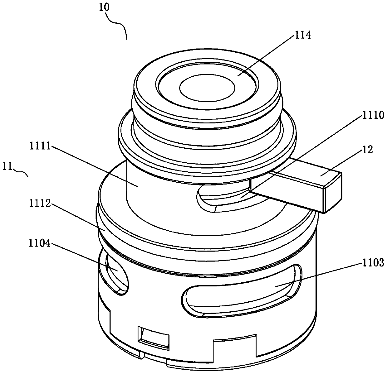
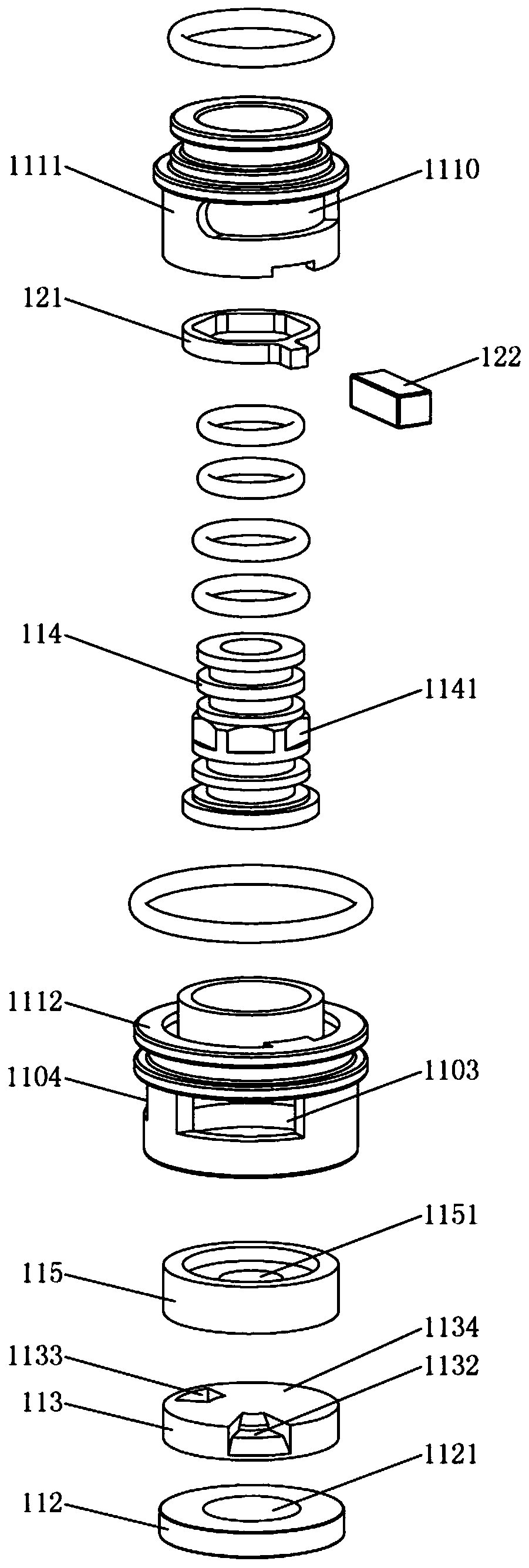
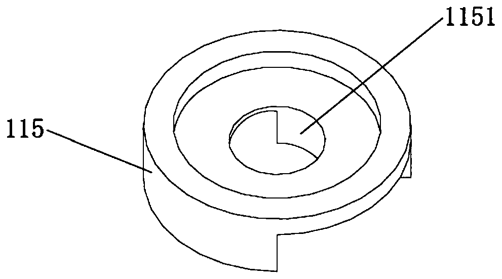
The invention discloses a temperature-regulating valve element and a shower. In the temperature-regulating valve element, a first rotary part, a first water passing path and a second water passing path are arranged in the first valve body; the first water passing path and the second water passing path are separately used for receiving cold water and hot water; water inlet ends of the first water passing path and the second water passing path are separately positioned at the two ends of the first valve body; a first water passing hole and a second water passing hole are formed in the side wallsof the first valve body; a first operating part is fixedly connected or is in non-rotation connection to a first rotary part and is provided with a first operating end extending to the outside of theside wall of the first valve body; and while the first rotary part is controlled to rotate on the plane perpendicular to the axis of the first valve body, a through-flow area, in the first water passing hole, of the first water passing path, and a through-flow area, in the second water passing hole, of the second water passing path are changed. The shower adopts the temperature-regulating valve element between a tube joint and a shower body. According to the technical scheme adopted by the invention, the temperature-regulating valve element can be arranged between the shower body and the water inlet tube joint, so that the problem that an operating part on the temperature-regulating valve element is easily touched to cause temperature-regulating failure in a using process of the shower issolved.

Description

technical field [0001] The invention relates to the technical field of sanitary ware, in particular to a temperature regulating valve core and a shower. Background technique [0002] The operating handle of the traditional shower is usually arranged on the front or end of the shower body, which has the following defects: (1) the user often accidentally touches the operating handle during daily use, causing the Shower parameters such as flow or temperature change, causing the user to adjust the position of the operating handle again to readjust the shower parameters such as appropriate flow or temperature, and the user's experience is not good; (2) the operating handle and its corresponding valve core When it is installed on the main body, it needs to occupy a large space. Therefore, it is usually necessary to design a shower body with a large volume, and the overall structure is heavy and not beautiful enough; (3) the operating handle is located on the shower body, and the o...

Claims


Application Information

Patent Timeline
Patent Type & Authority Applications(China)
IPC IPC(8): F16K3/06F16K3/314E03C1/02E03C1/05
CPCF16K3/06F16K3/314E03C1/05E03C1/021E03C1/023
Inventor 林孝发林孝山郑君邓小清刘启乔
Owner FUJIAN XIHE SANITARY WARE TECH
Learn More