
Double-temperature-state unit heat exchange station

A technology of heat exchange station and temperature state, which is applied in household heating, household heating, heating methods, etc., and can solve problems such as low system operation efficiency, project failure, and lack of efficient, fast, and accurate monitoring methods

Pending Publication Date: 2018-09-21
CHINA OPTIMIZED ENERGY
View PDF0 Cites 0 Cited by
  • Summary
  • Abstract
  • Description
  • Claims
  • Application Information

AI Technical Summary

Problems solved by technology

[0002] At present, for the traditional central air-conditioning system, the machine room part is usually non-standardized and tailored according to different sites, resulting in high requirements for installation workers on site; now, there is a growing shortage of blue-collar technical talents, and the speed of market engineering construction is accelerating. , the lack of technical personnel is one of the main reasons for the failure of the project. The main function of the central air-conditioning heat exchange station is to provide heat to the end user when the design requirements are met. Most of the similar products on the market currently have operating conditions and The design conditions do not match, and the system operation cannot adapt to changes in the environment and end-user needs, resulting in a serious imbalance in the hydraulic and thermal power of the system, resulting in high energy consumption and low efficiency. At the same time, the system mostly uses manual control based on manual experience judgment, control means and Single control target, lack of efficient, fast, and accurate monitoring methods, resulting in low system operation efficiency and serious delays, causing adverse effects on the user end

Method used


Image

  • Double-temperature-state unit heat exchange station
  • Double-temperature-state unit heat exchange station

Examples


Embodiment Construction

[0012] Embodiments of the present invention are described in detail below, examples of which are shown in the drawings, wherein the same or similar reference numerals designate the same or similar elements or elements having the same or similar functions throughout. The embodiments described below by referring to the figures are exemplary only for explaining the present invention and should not be construed as limiting the present invention.

[0013] In the description of the present invention, unless otherwise specified and limited, it should be noted that the terms "installation", "connection" and "connection" should be understood in a broad sense, for example, it can be mechanical connection or electrical connection, or two The internal communication of a component can be directly connected or indirectly connected through an intermediary. Those of ordinary skill in the art can understand the specific meanings of the above terms according to specific situations.

[0014] se...


PUM


Abstract

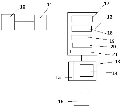
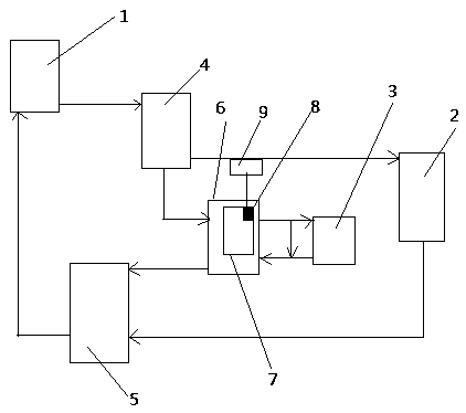
The invention relates to a double-temperature-state unit heat exchange station. The double-temperature-state unit heat exchange station comprises an air conditioner cold and heat source, an air exchange fan, an air conditioner radiation terminal, a first water mixing tank, a second water mixing tank and plate heat exchanger and is characterized in that the air conditioner cold and heat source is connected with the cold and heat source water inlet of the first water mixing tank, medium water entering the first water mixing tank is divided into two parts in a pressure stabilized manner, one partof the medium water is fed into the air exchange fan through the air exchange fan water outlet of the first water mixing tank and returns into the air conditioner cold and heat source through the second water mixing tank, the other part of the medium water enters the primary water inlet and the primary water outlet of the plate heat exchanger through the heat exchanger water outlet of the first water mixing tank and returns the air conditioner cold and heat source through the heat exchanger water return port of the second water mixing tank, and a primary circulating loop is formed; the secondary water inlet and the secondary water outlet of the plate heat exchanger are connected with the air conditioner radiation terminal to form a secondary circulating loop, a temperature regulating function is achieved through the air conditioner radiation terminal, a circulating water pump and an automatic water supplementing device are arranged in the plate heat exchanger, and the automatic watersupplementing device comprises a water level sensor and a water filling pump.

Description

technical field [0001] The invention relates to the technical field of air conditioning and ventilation, in particular to a dual-temperature unit heat exchange station. Background technique [0002] At present, for the traditional central air-conditioning system, the machine room part is usually non-standardized and tailored according to different sites, resulting in high requirements for installation workers on site; now, there is a growing shortage of blue-collar technical talents, and the speed of market engineering construction is accelerating. , the lack of technical personnel is one of the main reasons for the failure of the project. The main function of the central air-conditioning heat exchange station is to provide heat to the end user when the design requirements are met. Most of the similar products on the market currently have operating conditions and The design conditions do not match, and the system operation cannot adapt to changes in the environment and end-u...

Claims


Application Information

Patent Timeline
IPC IPC(8): F24D19/10
CPCF24D19/1015
Inventor 杨健
Owner CHINA OPTIMIZED ENERGY
Learn More