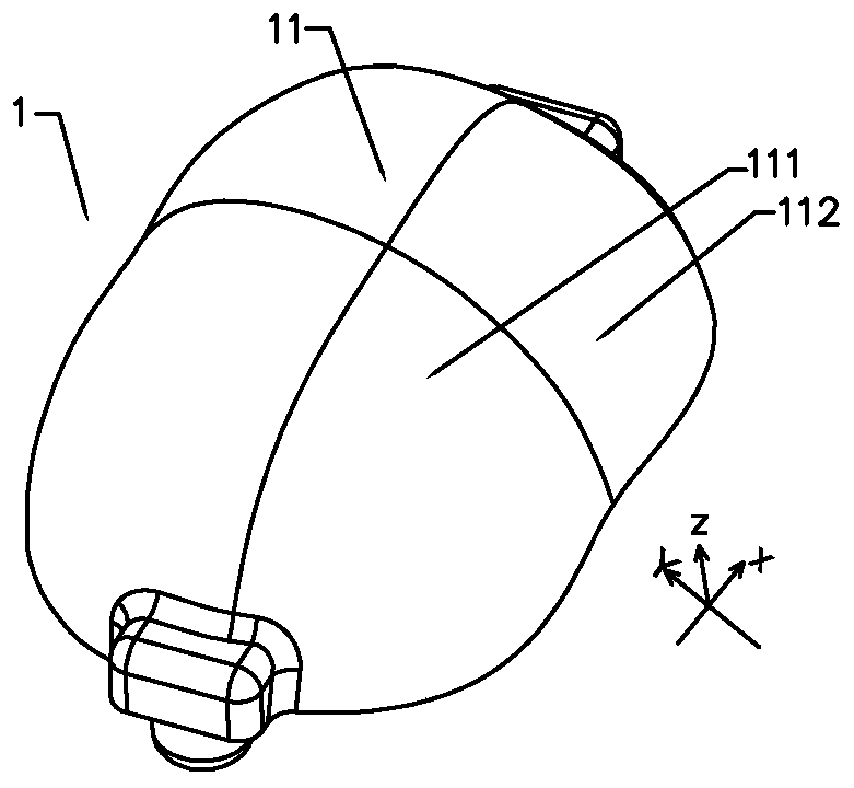
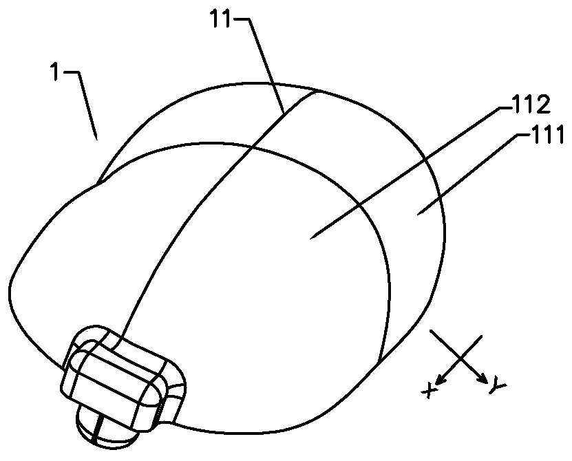
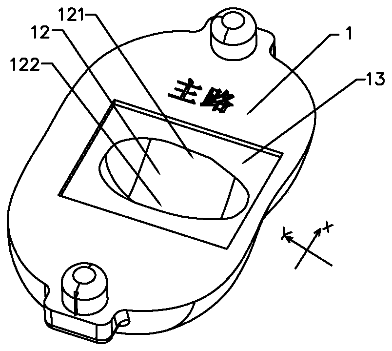
Lens unit applied to main road working condition, lens assembly and streetlamp holder

A technology of lens units and working conditions, which is applied to the parts of lighting devices, semiconductor devices of light-emitting elements, lighting and heating equipment, etc., can solve the problem of insufficient research on light distribution requirements for double-sided installation, and the lighting effect cannot meet the desired requirements. , spherical lamps lack light distribution research and other problems, to achieve the effect of high light utilization, consistent direction, easy installation and firmness

Pending Publication Date: 2020-07-28
ZHUHAI JINSHENG LIGHTING EQUIP
View PDF0 Cites 0 Cited by
  • Summary
  • Abstract
  • Description
  • Claims
  • Application Information

AI Technical Summary

Problems solved by technology

However, the existing spherical lamps basically lack specific light distribution research. The lighting conditions required for urban main roads (hereinafter referred to as "main road conditions"): eight lanes (28 meters wide), and the installation distance of lighting fixtures is large (two The ratio of the distance between the lamps to the height of the lamps is greater than 3), and the research on the light distribution requirements of the double-sided installation is not enough, resulting in the lighting effect not meeting the desired requirements, and failing to meet the requirements of the "Urban Road Lighting Design Standard" CJJ45-2015 index of

Method used


Image

  • Lens unit applied to main road working condition, lens assembly and streetlamp holder
  • Lens unit applied to main road working condition, lens assembly and streetlamp holder
  • Lens unit applied to main road working condition, lens assembly and streetlamp holder

Examples


no. 1 example

[0158] refer to Figure 12 , Figure 12 is a structural diagram of the first embodiment of the lens assembly. The lens assembly includes a substrate 15, a light-emitting device and a plurality of lens units 16 manufactured according to the above-mentioned embodiment of the lens unit. The substrate 15 is arranged in a ring shape, and multiple light-emitting devices are electrically connected to the substrate 15. Evenly distributed in the circumferential direction, the lens unit 16 is covered with the light-emitting device, so that the lens unit 16 is uniformly distributed in the circumferential direction, and the installation form of multiple lens units 16 is consistent (that is, when multiple lens units are installed, the positive direction of the minor axis faces consistent, and the positive direction of the major axis is in the same direction), that is, Figure 12 The settings shown; the installation form is consistent, which can make the direction of the light emitted by ...

no. 2 example

[0160] refer to Figure 13 , Figure 13 is a structural diagram of the second embodiment of the lens assembly. The lens assembly includes a substrate 17, a light-emitting device, and a plurality of lens units 18 made according to the above-mentioned embodiment of the lens unit. The substrate 17 is arranged in a strip shape, and four light-emitting devices are electrically connected to the substrate 17. The four light-emitting devices Distributed in sequence along the same direction, lens units 18 are arranged on the outer casing of the light-emitting device, so that the lens units 18 are arranged in sequence along the same direction, and multiple lens units 18 are installed in the same form, which can make the direction of the light emitted by the lens units consistent, that is, as Figure 10 settings shown. When the lens assembly is applied to a spherical lamp and the spherical lamp is applied to a main road, the short axis direction of the lens unit 18 corresponds to the r...


PUM


Abstract

The invention provides a lens unit applied to a main road working condition. The lens unit is provided with an inner cavity used for containing a light-emitting device, and the lens unit comprises anincident surface positioned on the inner surface of the lens unit and an emergent surface positioned on the outer surface of the lens unit; when the light-emitting device is installed on the lens unit, the projection of the center of the light-emitting device on the bottom plane of the lens unit is positioned on the short axis of the lens unit, and the distance L deviating from the geometric center of the bottom plane of the lens unit meets the condition that L is larger than 0 mm and smaller than or equal to 2mm; and a light beam emitted from the light-emitting device is incident to the incident surface at an incident angle with the value range of -60 to 60 degrees, then is refracted at a refraction angle with the value range of -60.253 to 63.656 degrees correspondingly, and then is emitted from the emergent surface at an emergent angle with the value range of -79.35 to 79.35 degrees correspondingly, so that light rays are effectively projected to the road surface after light distribution, and the illumination efficiency is effectively improved.

Description

technical field [0001] The invention relates to the field of road lighting, in particular to a lens unit used in main road conditions, a lens assembly equipped with a plurality of lens units, and a street lamp lamp holder equipped with lens units. Background technique [0002] LED lights have the characteristics of long life and power saving, and have been widely used in various fields in recent years. Especially with the continuous implementation of the national semiconductor lighting project, the LED road lighting bidding project of the National Development and Reform Commission, and the LED street lamp project of ten cities and ten thousand lamps, road lighting lamps such as LED street lamps have gradually become popular due to their advantages of high efficiency, energy saving, and high color rendering. It is widely used in urban road lighting, especially on urban main roads (8 lanes); and it is basically a street lamp with an installation elevation angle. [0003] Beca...

Claims


Application Information

Patent Timeline
Patent Type & Authority Applications(China)
IPC IPC(8): F21V5/04F21S8/08F21W131/103F21Y115/10
CPCF21S8/085F21V5/04F21W2131/103F21Y2115/10
Inventor 畅育科
Owner ZHUHAI JINSHENG LIGHTING EQUIP
Why Eureka
Try Eureka