A Flexible Networking System Inside Electric Enterprises with Multiple Distribution Transformers

A technology of distribution transformers and isolation transformers, applied in the direction of power transmission AC network, single AC network with different frequencies, etc., can solve the problems of uneven distribution of distribution transformers, paralysis of power distribution system, uneven load of distribution transformers, etc. Achieve the effect of improving the utilization rate of power assets, alleviating power supply pressure, and reducing fixed electricity charges

Active Publication Date: 2022-05-13
湖北春田电工技术有限公司
View PDF4 Cites 0 Cited by
  • Summary
  • Abstract
  • Description
  • Claims
  • Application Information

AI Technical Summary

Problems solved by technology

[0004] In the current multi-distribution transformer power grid system, the distribution transformers operate independently and are not connected to each other. The entire distribution system presents a radial structure. If some distribution transformers fail and power outages, the The multiple electrical loads connected to the distribution transformer will be out of service for a short time or for a long time; in addition, there is no effective means to redistribute the electric energy when there is uneven load between different distribution transformers; except for cutting off part of the electrical load In addition to reducing the load on distribution transformers, there is no other means to ensure distribution safety
Although a small number of enterprises will adopt the direct parallel operation of some low-voltage buses, this operation mode will bring the following problems: First, there may be uneven distribution between the two distribution transformers, and the distribution transformer with more output is prone to failure ; Second, once one of the distribution transformers fails, the entire distribution system will be completely paralyzed

Method used


Image

  • A Flexible Networking System Inside Electric Enterprises with Multiple Distribution Transformers
  • A Flexible Networking System Inside Electric Enterprises with Multiple Distribution Transformers
  • A Flexible Networking System Inside Electric Enterprises with Multiple Distribution Transformers

Examples


Embodiment 1

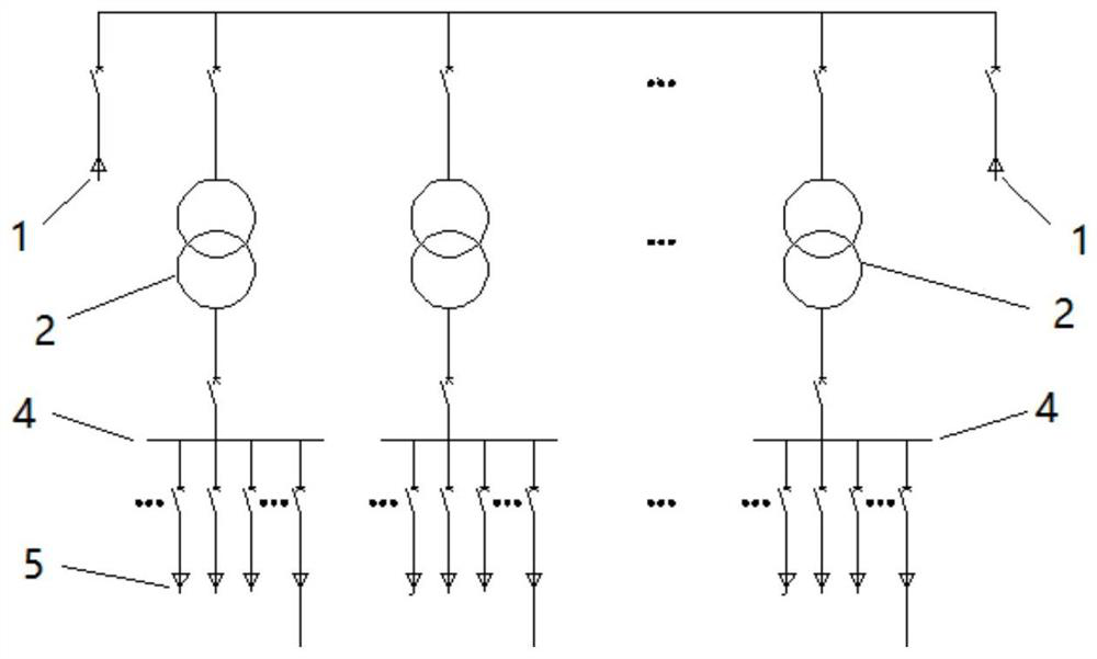
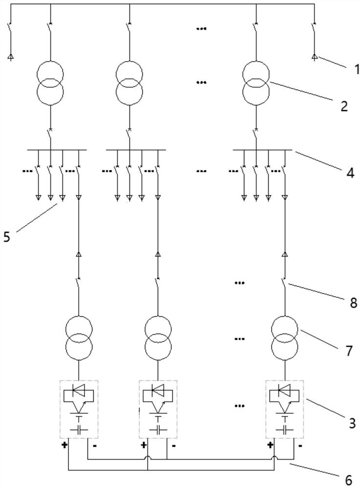
[0031] figure 2 It is a schematic diagram of the structure of the internal flexible networking system of the electricity enterprise with multiple distribution transformers provided in this embodiment. In this embodiment, the power distribution system using a primary transformer is used as an example for illustration; see figure 2 , the internal flexible networking system of the power consumption enterprise includes high-voltage cabinets, n distribution transformers 2, low-voltage cabinets equal in number to distribution transformers 2, and first bidirectional converters 3, wherein n is a natural number greater than 1, and n The value depends on the number and location distribution of the internal power loads of the power consumption enterprise; the 6-10KV voltage provided by the public grid is connected to the high-voltage cabinet through the distribution line, and then the voltage is reduced to 380 / 220V through the distribution transformer 2 and then sent to the In the corr...

Embodiment 2

[0038] Figure 4 It is a schematic structural diagram of the internal flexible networking system of the electricity enterprise with multiple distribution transformers 2 provided in this embodiment, as shown in Figure 4 As shown, compared with the first embodiment, the internal flexible networking system of the power consumption enterprise provided by this embodiment has at least one energy storage converter 9 connected to the DC bus 6, and the energy storage converter 9 passes through the DC bus 6 is interconnected with each first bidirectional converter 3; the energy storage converter 9 is a DC / DC voltage-controllable bidirectional converter, and the energy storage converter 9 realizes the regulation and control of the DC bus 6 voltage Time-domain regulation of the power distribution network, and planned charging and discharging of the energy storage battery built in the energy storage converter 9, such as charging the energy storage battery when the electricity load is low ...

Embodiment 3

[0040] Figure 5 It is a schematic structural diagram of the internal flexible networking system of the electricity enterprise with multiple distribution transformers 2 provided in this embodiment, as shown in Figure 5 As shown, compared with the first embodiment, the internal flexible networking system provided by this embodiment includes at least one second bidirectional converter 10. The second bidirectional converter 10 can be AC / DC DC-side controllable bidirectional converter with four-quadrant operation on the AC side, or a DC / DC voltage-controllable bidirectional converter; one port of the second bidirectional converter 10 is connected to the DC bus 6. The port on the other side serves as the port 11 for connecting different forms of distributed new energy. The electric energy provided by the distributed new energy is first connected to the internal flexible networking system of the power consumption enterprise through the second bidirectional converter 10 and the DC ...


PUM


Abstract

The invention discloses an internal flexible networking system of a power consumption enterprise with multiple distribution transformers, which includes a plurality of distribution transformers, and the low-voltage side of each distribution transformer is used to connect with a power supply bus to provide Electric load distribution; also includes a first bidirectional converter; the AC side port of each of the first bidirectional converters is electrically connected to the power supply bus corresponding to a distribution transformer, and each first bidirectional converter The DC side ports of converters are interconnected through DC busbars, so that a mesh distribution network is formed between a plurality of distribution transformers; a mesh connection network is formed between a plurality of distribution transformers in the present invention, and each distribution transformer All of them can be flexibly connected to each other, and the electric energy in the system can be migrated and distributed among the distribution transformers along the grid-shaped distribution network, so as to realize mutual support of power, energy interaction, mutual support of voltage, and mutual emergency backup, ensuring that enterprises Power distribution security and improved power asset utilization.

Description

technical field [0001] The invention belongs to the technical field of smart grids, and more specifically relates to a flexible networking system inside a power-consuming enterprise with multiple distribution transformers. Background technique [0002] The power supply and distribution system is generally composed of high-voltage distribution stations, high-voltage distribution lines, low-voltage substations, low-voltage distribution lines and electrical equipment. According to the voltage level provided by the public grid, at present, enterprises may need to carry out primary transformation or secondary transformation; the so-called primary transformation means that the 6-10KV voltage provided by the public grid is reduced to 380 / 220V voltage, and the electric energy is directly distributed to each Use of low-voltage electrical equipment; the secondary transformation needs to first reduce the 35-110KV voltage provided by the public grid to 6-10KV voltage, and then reduce th...

Claims


Application Information

Patent Timeline
Patent Type & Authority Patents(China)
IPC IPC(8): H02J3/02H02J3/34
CPCH02J3/02H02J3/34
Inventor 余腾飞朱道维谭华朱劲松李杨
Owner 湖北春田电工技术有限公司
Why Eureka
Try Eureka