Automatic pot removing equipment for potted plants

A technology of equipment and bottom plate, which is applied in the field of automatic depotting equipment, can solve the problems of low depotting efficiency and easy damage of root system of potted plants, and achieve the effect of improving depotting efficiency

Active Publication Date: 2020-07-31
张玉娥
View PDF7 Cites 5 Cited by
  • Summary
  • Abstract
  • Description
  • Claims
  • Application Information

AI Technical Summary

Problems solved by technology

[0003] In order to make the garden greener, it is necessary to plant some flowers and plants in the garden. At present, when the landscaping is greened, the potted plants are usually taken out from the flowerpot and planted in the garden. Use a knif

Method used


Image

  • Automatic pot removing equipment for potted plants
  • Automatic pot removing equipment for potted plants
  • Automatic pot removing equipment for potted plants

Examples


Embodiment 1

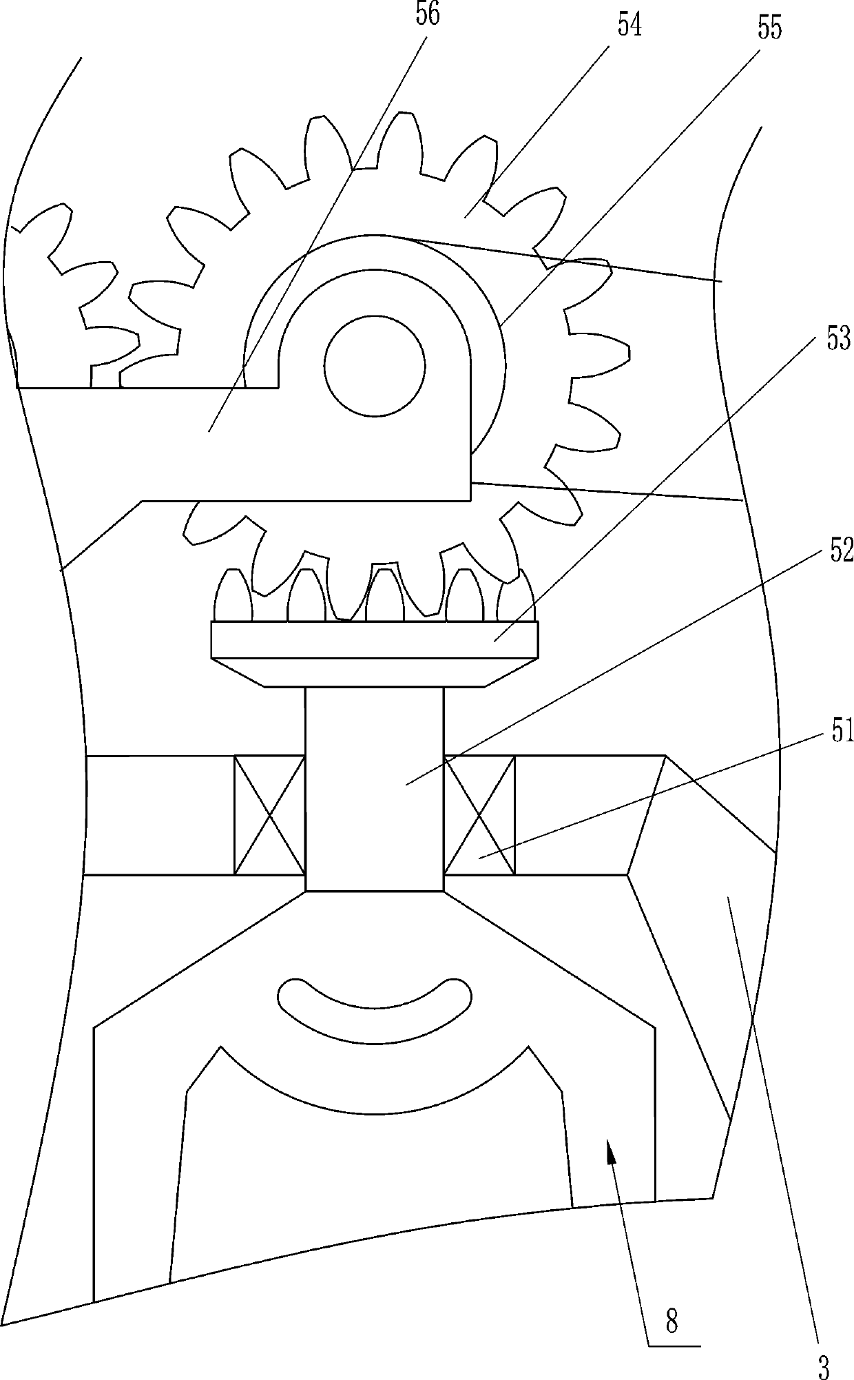
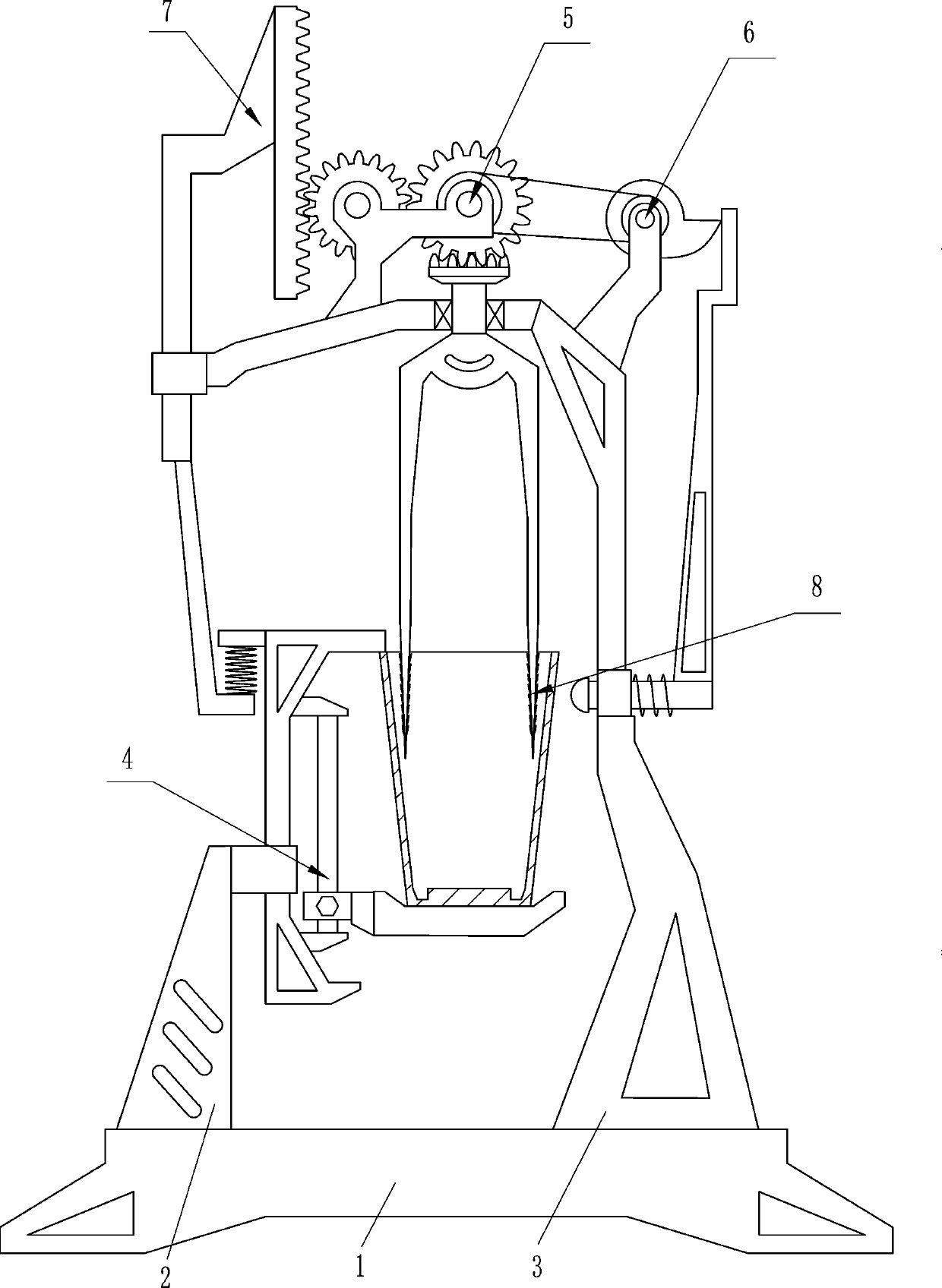
[0026] A potted plant automatic potting device, such as figure 1 As shown, it includes a base plate 1, a first support 2, a second support 3, a carrying device 4, a rotating device 5 and a knocking device 6, the left side of the base plate 1 top is equipped with the first support 2, and the right side of the base plate 1 top The second support 3 is installed, the upper right wall of the first support 2 is equipped with a bearing device 4 , the top of the second support 3 is equipped with a rotating device 5 , and the knocking device 6 is installed on the right wall of the second support 3 .

[0027] When it is necessary to take off the potted plants, the user places the flower pots on the bearing device 4, and then the user starts the rotating device 5 to make the knocking device 6 knock the flower pots, so that the flower pots can be vibrated, so that the potted plants can be carried out. Take off the pot, and can protect the root system of the potted plant from being damaged...

Embodiment 2

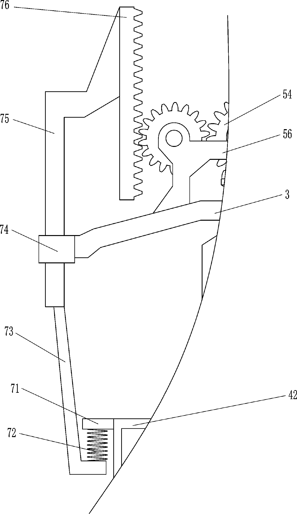
[0035] On the basis of Example 1, such as Figure 6As shown, pressure device 7 is also included, and pressure device 7 includes horizontal plate 71, second spring 72, connecting rod 73, second sliding sleeve 74, second sliding rod 75 and rack 76, and horizontal plate 71 is arranged on the second The left wall upper part of a slide bar 42, the bottom of horizontal plate 71 is equipped with second spring 72, and the bottom end of second spring 72 is fixed with connecting rod 73, and second sliding sleeve 74 is fixed on the left wall of second support 3, and the second The sliding type is provided with the second slide bar 75 in two slide sleeves 74, and the top end of the second slide bar 75 is affixed with the top of connecting rod 73, and the right wall top of the second slide bar 75 is provided with rack 76, and rack 76 Meshes with the first gear 54 on the left.

[0036] Such as Figure 7 As shown, a fixing device 8 is also included. The fixing device 8 includes a pointed c...


PUM


Abstract

The invention relates to automatic pot removing equipment, in particular to automatic pot removing equipment for potted plants. The technical problem to be solved by the invention is how to provide the potted plant automatic pot removing equipment capable of protecting potted plant root systems while improving pot removing efficiency. The automatic pot removing equipment for potted plants comprises a bottom plate, a first support, a second support, a bearing device, a rotating device, a knocking device and the like. The first support is mounted at the top of the bottom plate; the second support is mounted at the top, away from the first support, of the bottom plate; the bearing device is mounted on the first support; the rotating device is mounted on the upper portion of the second support; and the knocking device is mounted on the side wall, close to the rotating device, of the second support. The potted plant can be fixed through the bearing device, and the potted plant can be knocked through cooperation of the rotating device and the knocking device to vibrate the flowerpot, so that the potted plants can be taken out of the corresponding flowerpots.

Description

technical field [0001] The invention relates to an automatic pot removal device, in particular to an automatic pot removal device. Background technique [0002] The definition of potted plants refers to the general term for living plants planted in pots; potted plants must be living plants, which are different from potted flowers (which can be artificial flowers). [0003] In order to make the garden green better, it is necessary to plant some flowers and plants in the garden. At present, when the landscaping is greened, the potted plants are usually taken out from the flowerpot and planted in the garden. Use a knife to divide the potted plants at the edge of the pot, and take out the potted plants from the potted plants in this way, and the root system of the potted plants taken out in this way is easy to damage, and the potted plants taken out of the potted plants in this way are less efficient. [0004] Therefore need to research and develop a kind of can protect potted ...

Claims


Application Information

Patent Timeline
IPC IPC(8): A01G9/06A01G9/08
CPCA01G9/06A01G9/086A01G9/088
Inventor 张玉娥
Owner 张玉娥
Why Eureka
Try Eureka