Head and neck suspension device for department of cerebral surgery

A suspension device and brain surgery technology, which is applied in the field of medical equipment, can solve the problems of inconvenient adjustment of the height of the suspension belt and high production costs, and achieve the effects of improving the safety of use, reducing difficulty, and increasing friction

Inactive Publication Date: 2020-07-31
诸暨市人民医院
View PDF5 Cites 3 Cited by
  • Summary
  • Abstract
  • Description
  • Claims
  • Application Information

AI Technical Summary

Problems solved by technology

[0004] The invention proposes a head and neck suspension device for brain surgery, which solves the problems of high product

Method used


Image

  • Head and neck suspension device for department of cerebral surgery
  • Head and neck suspension device for department of cerebral surgery
  • Head and neck suspension device for department of cerebral surgery

Examples


Embodiment 1

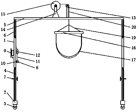
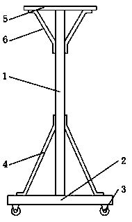
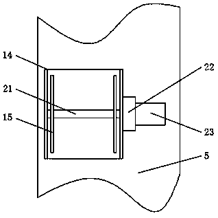
[0033] refer to Figure 1-8 , a head and neck suspension device for brain surgery, comprising two supporting legs 1, the bottom of the supporting legs 1 is welded with a stabilizer bar 2, and the bottom of the supporting legs 1 is movably installed with two universal casters 3, the supporting legs 1 and the stabilizer bar 2 are fixed with two first slanting beams 4 by the first screw, and the top of the two support legs 1 is fixed with the same top plate 5 by the second screw, and the support leg 1 and the top plate 5 pass through The third screw is fixed with two second slanting beams 6, the support leg 1 is provided with a clamping mechanism 7, and one side of the support leg 1 is welded with a storage plate 8, and the other side of the support leg 1 is provided with a winding Frame 9, control switch 10 is arranged on the storage plate 8, is connected with noodle line 11 on the control switch 10, and is provided with take-up box 12 on the noodle line 11, and the top of top p...

Embodiment 2

[0036] refer to Figure 1-9 , a head and neck suspension device for brain surgery, comprising two supporting legs 1, the bottom of the supporting legs 1 is welded with a stabilizer bar 2, and the bottom of the supporting legs 1 is movably installed with two universal casters 3, the supporting legs 1 and the stabilizer bar 2 are fixed with two first slanting beams 4 by the first screw, and the top of the two support legs 1 is fixed with the same top plate 5 by the second screw, and the support leg 1 and the top plate 5 pass through The third screw is fixed with two second slanting beams 6, the support leg 1 is provided with a clamping mechanism 7, and one side of the support leg 1 is welded with a storage plate 8, and the other side of the support leg 1 is provided with a winding Frame 9, control switch 10 is arranged on the storage plate 8, is connected with noodle line 11 on the control switch 10, and is provided with take-up box 12 on the noodle line 11, and the top of top p...


PUM


Abstract

The invention belongs to the technical field of medical equipment, in particular to a head and neck suspension device for a department of cerebral surgery. Aiming at the problems that an existing headand neck suspension mechanism is high in production cost and the height of a suspension sling is inconvenient to adjust, the head and neck suspension device comprises two support legs, wherein the bottom of each support leg is welded with a stabilizer bar; two swivel casters are movably arranged at the bottom of each support leg; two first oblique beams are fixedly arranged between each support leg and the corresponding stabilizer bar through first bolts; a same top plate is fixedly arranged at the tops of the two support legs through second bolts; two second oblique beams are fixedly arranged between each support leg and the top plate through third bolts; a clamping mechanism is arranged on each support leg; and a placement plate is welded at one side of one support leg and a winding frame is arranged at the other side of the support leg. According to the head and neck suspension device for the department of cerebral surgery, the production cost of the head and neck suspension mechanism is reduced, the difficulty in height adjustment of the suspension sling is reduced, the overall use safety is improved, and the head and neck suspension device is simple in structure and high in practicability.

Description

technical field [0001] The invention relates to the technical field of medical instruments, in particular to a head and neck suspension device for brain surgery. Background technique [0002] Medical devices refer to instruments, equipment, utensils, in vitro diagnostic reagents and calibrators, materials, and other similar or related items that are directly or indirectly used on the human body, including the required computer software. The medical device industry involves medicine, machinery, electronics, etc. It is a multidisciplinary, knowledge-intensive, and capital-intensive high-tech industry. The head and neck suspension mechanism is a kind of medical device used for patient rehabilitation. [0003] The current head and neck suspension mechanism is usually integrated with the nursing bed, and the head and neck suspension mechanism is fixed on the nursing bed. The production cost is high, which is not conducive to actual use. Secondly, the height adjustment of the sus...

Claims


Application Information

Patent Timeline
IPC IPC(8): A61G7/07
CPCA61G7/072
Inventor 杨刚
Owner 诸暨市人民医院
Why Eureka
Try Eureka