
Assembly line belt cleaning machine

An assembly line and cleaning machine technology, applied in cleaning devices, conveyor objects, transportation and packaging, etc., can solve problems such as belt aging, stubborn residue that cannot be embedded in the belt, cleaning is not thorough enough, etc., to achieve a thorough cleaning effect

Inactive Publication Date: 2020-07-31
唐本春
View PDF0 Cites 6 Cited by
  • Summary
  • Abstract
  • Description
  • Claims
  • Application Information

AI Technical Summary

Problems solved by technology

[0003] After the belt is used for a long time, some dust and residue will remain on the surface, which will easily cause the belt to age. Currently, scrapers and brushes are used to clean the belt, but the scraper and brush cannot remove the stubborn residue embedded in the belt, and the cleaning is not thorough enough.

Method used

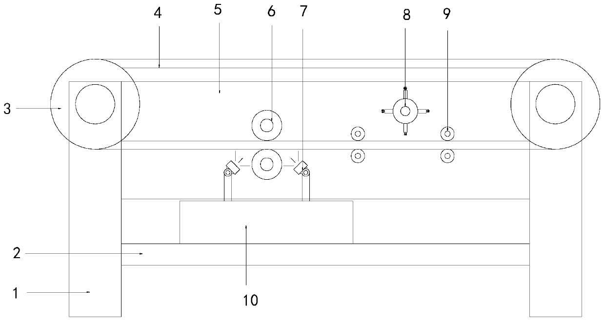
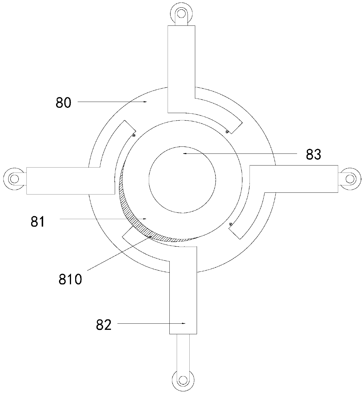
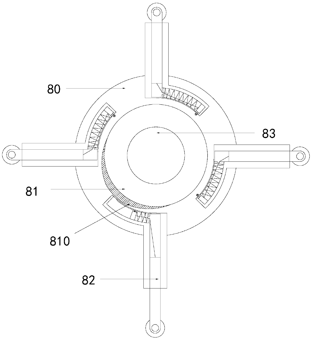

Image

  • Assembly line belt cleaning machine
  • Assembly line belt cleaning machine
  • Assembly line belt cleaning machine

Examples


Embodiment 1

[0027] See figure 1 , The present invention provides a technical solution for an assembly line belt cleaning machine: its structure includes a frame 1, a reinforcing plate 2, a guide wheel 3, a belt 4, a side plate 5, a brush roller 6, a nozzle 7, a shock structure 8, a clamping roller Group 9, water tank 10, the bottom of the frame 1 is welded with a reinforcement plate 2, the top of the frame 1 is welded with side plates 5 on both sides, the two ends of the frame 1 are respectively installed with guide wheels 3, the belt 4 The two ends of the water tank are respectively matched with the guide wheels 3, the water tank 10 is arranged on the reinforcing plate 2, the top two sides of the water tank 10 are respectively provided with nozzles 7, and the brush roller 6 is arranged on the upper and lower sides of the belt 4, so The shock structure 8 is fixed in the middle of the two side plates 5, and the two sides of the shock structure 8 are respectively provided with a clamping rol...

Embodiment 2

[0030] See Figure 1-5 , The present invention provides a technical solution for an assembly line belt cleaning machine: its structure includes a frame 1, a reinforcing plate 2, a guide wheel 3, a belt 4, a side plate 5, a brush roller 6, a nozzle 7, a shock structure 8, a clamping roller Group 9, water tank 10, the bottom of the frame 1 is welded with a reinforcement plate 2, the top of the frame 1 is welded with side plates 5 on both sides, the two ends of the frame 1 are respectively installed with guide wheels 3, the belt 4 The two ends of the water tank are respectively matched with the guide wheels 3, the water tank 10 is arranged on the reinforcing plate 2, the top two sides of the water tank 10 are respectively provided with nozzles 7, and the brush roller 6 is arranged on the upper and lower sides of the belt 4, so The shock structure 8 is fixed in the middle of the two side plates 5, and the two sides of the shock structure 8 are respectively provided with a clamping ...


PUM


Abstract

The invention discloses an assembly line belt cleaning machine. The assembly line belt cleaning machine structurally comprises machine frames, a reinforcing plate, guide wheels, a belt, side plates, brush rolls, spray heads, a hitting vibrating structure, clamping roller sets and a water tank, wherein the reinforcing plate is welded to the bottom of the machine frame, the side plates are welded tothe two sides of the machine frame, the two ends of the machine frames are correspondingly provided with the guide wheels, the two ends of the belt are respectively matched with the guide wheels, thewater tank is disposed on the reinforcing plate, the two sides of the top of the water tank are respectively provided with the spray heads, the brush rollers are arranged on the upper side and the lower side of the belt, the hitting vibrating structure is fixed to the middle of the two side plates, the clamping roller sets are arranged on the two sides of the hitting vibrating structure respectively, and the clamping roller sets are matched with the belt. The assembly line belt cleaning machine has the beneficial effects that stubborn residues clamped in the belt can be punched through the hitting vibrating structure, so that the cleaning is more thorough; and by the design of the hitting vibrating structure, only when the assembly line belt cleaning machine passes through the bottom, itis guarantees that the belt on the top works normally.

Description

Technical field [0001] The invention relates to the field of cleaning equipment, in particular to an assembly line belt cleaning machine. Background technique [0002] The belt assembly line is a kind of assembly line, which occupies a large market. Therefore, various large enterprises have transformed and used assembly lines to save labor and improve work efficiency. It can transport a wide variety of materials, not only can transport all kinds of bulk materials, but also can transport various light-weight products such as cartons, packaging bags, etc., and can also be used to transport goods at the cashier of large supermarkets. It has a wide range of uses. [0003] After long-term use of the belt, some dust and residue will remain on the surface of the belt, which can easily cause the belt to age. Currently, scrapers and brushes are used for cleaning, but the scrapers and brushes cannot brush out the stubborn residue embedded in the belt, and the cleaning is not thorough enough....

Claims


Application Information

Patent Timeline
Patent Type & Authority Applications(China)
IPC IPC(8): B65G45/22B65G45/18B65G45/24B65G45/10
CPCB65G45/10B65G45/18B65G45/22B65G45/24
Inventor 唐本春
Owner 唐本春
Learn More