Lockup Pressure Control Method of Lockup Clutch in Torque Converter

A technology for locking clutches and torque converters, applied in clutches, transmission control, components with teeth, etc., to achieve the effect of reducing impact and high robustness

Active Publication Date: 2022-03-15
UNITED AUTOMOTIVE ELECTRONICS SYST
View PDF0 Cites 0 Cited by
  • Summary
  • Abstract
  • Description
  • Claims
  • Application Information

AI Technical Summary

Problems solved by technology

[0005] The object of the present invention is to provide a lock-up pressure control method for a lock-up clutch in a hydraulic torque converter, so as to solve the problems of using the lock-up clutch in the prior art

Method used


Image

  • Lockup Pressure Control Method of Lockup Clutch in Torque Converter
  • Lockup Pressure Control Method of Lockup Clutch in Torque Converter
  • Lockup Pressure Control Method of Lockup Clutch in Torque Converter

Examples


Embodiment Construction

[0024] The method for controlling the lock-up pressure of the lock-up clutch in the hydraulic torque converter proposed by the present invention will be further described in detail below with reference to the drawings and specific embodiments. Advantages and features of the present invention will be apparent from the following description and claims. It should be noted that all the drawings are in a very simplified form and use imprecise scales, and are only used to facilitate and clearly assist the purpose of illustrating the embodiments of the present invention.

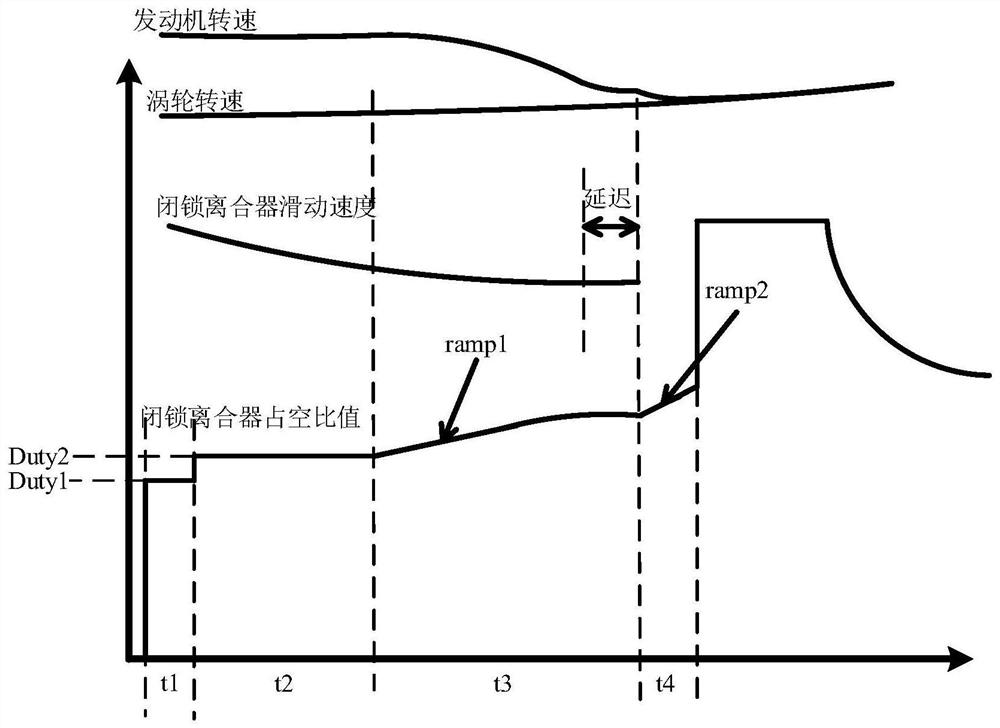
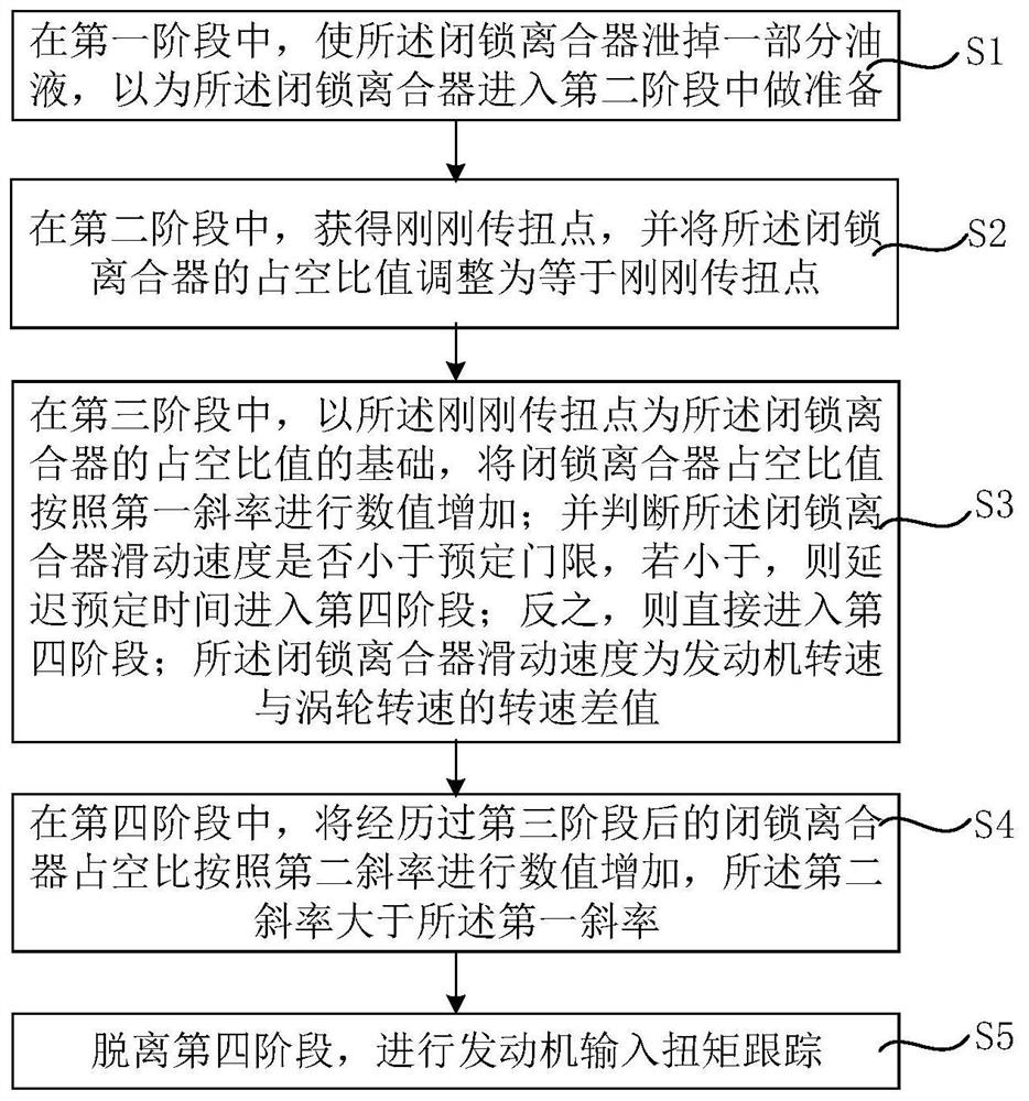
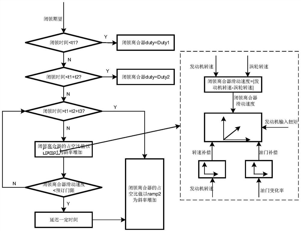
[0025] Please refer to figure 1 , figure 2 and image 3 , figure 1 It is a schematic diagram of the locking control of the locking clutch in an embodiment of the present invention; figure 2 It is a flowchart of a lockup pressure control method for a lockup clutch in a hydraulic torque converter in an embodiment of the present invention; image 3 It is a logic flow chart of a lockup pressure control method of...


PUM


Abstract

The present invention provides a lockup pressure control method of a lockup clutch in a hydraulic torque converter. In the third stage, the lockup clutch duty ratio is set to The ratio increases numerically according to the first slope; and it is judged whether the slipping speed of the lock-up clutch is less than a predetermined threshold, and if it is less, then delay the predetermined time to enter the fourth stage; otherwise, directly enter the fourth stage. In the third stage, the first slope adapts to the sliding speed of the lock-up clutch and the input torque of the engine, so that the lock-up clutch can be smoothly transitioned before being pressed, reaching a stable state, which reduces the impact caused by the fixed-slope pressing; in addition, with the second The torque transmission point just in the stage is based on the duty cycle value of the lock-up clutch to sweep the point to realize the locking control, which does not rely on the self-learning of the torque transmission point and has high robustness.

Description

technical field [0001] The invention relates to the technical field of automatic transmission control, in particular to a locking pressure control method of a locking clutch in a hydraulic torque converter. Background technique [0002] Automatic transmission (AT for short) is composed of hydraulic torque converter, planetary gear transmission and control mechanism. The automatic transmission can automatically change the speed and torque according to the road conditions, and the driver can concentrate on the road traffic without being confused by gear shifting. [0003] Among them, the hydraulic torque converter is an indispensable part of the AT as a low-speed torque increasing and buffering device in the automatic transmission. However, when the engine speed gradually increases, the oil churning loss will increase, and the efficiency of the torque converter will decrease without increasing the torque, further affecting the fuel consumption of the vehicle. Adding a lock-u...

Claims


Application Information

Patent Timeline
Patent Type & Authority Patents(China)
IPC IPC(8): F16D48/02F16H61/48F16H61/04
CPCF16D48/02F16H61/48F16H61/04F16H2061/0087F16H2061/0474
Inventor 王振锁杨庆邹绵意历宝录
Owner UNITED AUTOMOTIVE ELECTRONICS SYST
Why Eureka
Try Eureka