
Continuously variable power-split transmission

A kind of transmission equipment and shunt technology, which is applied in the direction of transmission devices, mechanical equipment, gear transmission devices, etc., can solve problems such as poor transmission efficiency, and achieve the effect of reducing complexity and reducing complexity

Active Publication Date: 2020-07-31
ZF FIEDRICHSHAFEN AG
View PDF11 Cites 0 Cited by
  • Summary
  • Abstract
  • Description
  • Claims
  • Application Information

AI Technical Summary

Problems solved by technology

[0004] Compared to purely mechanical transmissions, hydrostatic mechanically continuously variable power-split transmissions provide poorer transmission efficiency when operating in a hydrostatic power path due to the system

Method used


Image

  • Continuously variable power-split transmission
  • Continuously variable power-split transmission
  • Continuously variable power-split transmission

Examples


Embodiment Construction

[0037] Embodiments are described below with reference to the drawings. Identical or similar elements are marked with the same reference numerals in different figures.

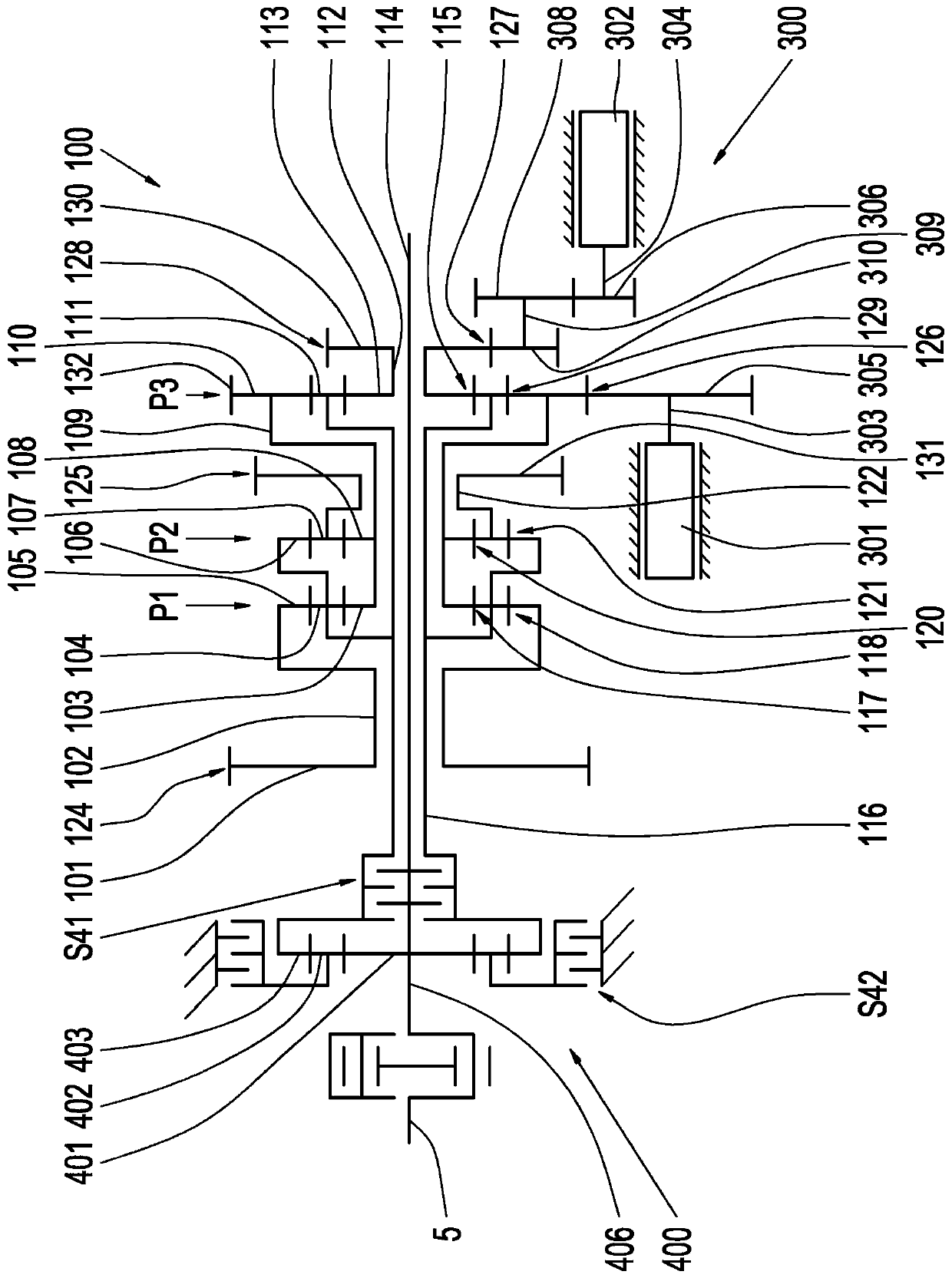
[0038] figure 1 A portion of a continuously variable power-split transmission is shown. More precisely, in figure 1 The planetary gear unit 100 , the reversing gear unit 400 and the transmission unit 300 are shown in FIG.

[0039] The transmission input shaft 5 is connected to the input shaft 406 of the reversing transmission device 400 . The reversing transmission 400 connects the input shaft 406 to the input shaft 116 of the planetary gear unit 100 so that the direction of rotation can be reversed. The reversing gear 400 is designed as a planetary gear, wherein the sun gear 401 is rotationally fixedly connected to the input shaft 406 . The planetary assembly 402 meshes with the sun gear 401 on the one hand and with the ring gear 403 on the other hand. Ring gear 403 is rotationally fixedly connected to i...


PUM


Abstract

A continuously variable power-split transmission having a planetary gear mechanism arrangement is described. The planetary gear mechanism arrangement has three planetary gear sets (P1, P2, P3), an input shaft (116; 816) and three output shafts (102, 112, 122). Furthermore, the transmission has a change-speed gearbox (500; 600; 700; 900) which is connected to the output shafts, a reverse gear mechanism and a variator. Each of the three planetary gear sets (P1, P2, P3) is assigned in each case one output shaft (102, 112, 122). The input shaft (116; 816) is operatively connected in each of the three planetary gear sets (P1, P2, P3) via in each case one gearwheel pairing (118, 121, 115) to in each case one output shaft (102, 112, 122). The transmission can be shifted with the use of the change-speed gearbox and the reverse gear mechanism (400; 1000) into at least eight driving ranges (FB1 to FB10). The variator (300) is set up to vary a transmission ratio of the transmission (1; 2; 3; 4) within the driving ranges (FB1 to FB10) in each case in a continuously variable manner. The variator (300) is operatively connected continuously to a single planetary gear set (P3) of the three planetary gear sets (P1, P2, P3).

Description

technical field [0001] The invention relates to a continuously variable power split type transmission device for working machinery. More precisely, the invention relates to a continuously variable split-split transmission with a planetary gear, a gearshift and a variator. Background technique [0002] Work machines such as construction machines or agricultural machines are increasingly being designed with continuously variable power-split drives. In agricultural technology, such continuously variable transmission systems are usually of the hydrostatic-power-split type. Such power-split transmissions decisively influence the efficiency curves of today's continuously variable power-split transmissions (so-called continuously variable transmissions). Typically, optimum efficiency with respect to the transmission ratio is only achieved when a relatively large proportion of the power to be directed is realized via the so-called mechanical power path. This mechanical power path...

Claims


Application Information

Patent Timeline
Patent Type & Authority Applications(China)
IPC IPC(8): F16H37/08B60K6/365B60K17/12B60K6/445F16H3/60
CPCB60K6/365B60K6/445F16H3/60F16H37/084F16H2037/0866Y02T10/62F16H3/728
Inventor B·里克S·贝克P·雷肯巴赫R·希梅尔斯巴赫
Owner ZF FIEDRICHSHAFEN AG
Learn More