A postoperative facial ice compress device
A face and cold compress technology, applied in the field of medical equipment, can solve problems such as sore hands and inconvenient operation
- Summary
- Abstract
- Description
- Claims
- Application Information
AI Technical Summary
Problems solved by technology
Method used
Image

Examples
Embodiment 1
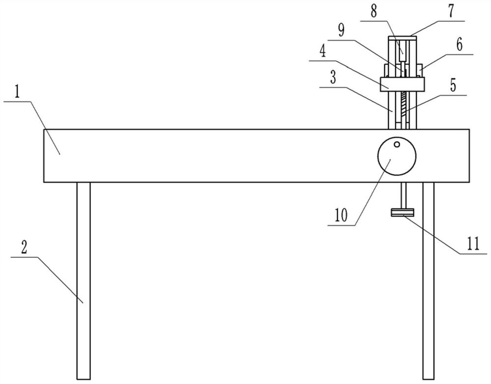
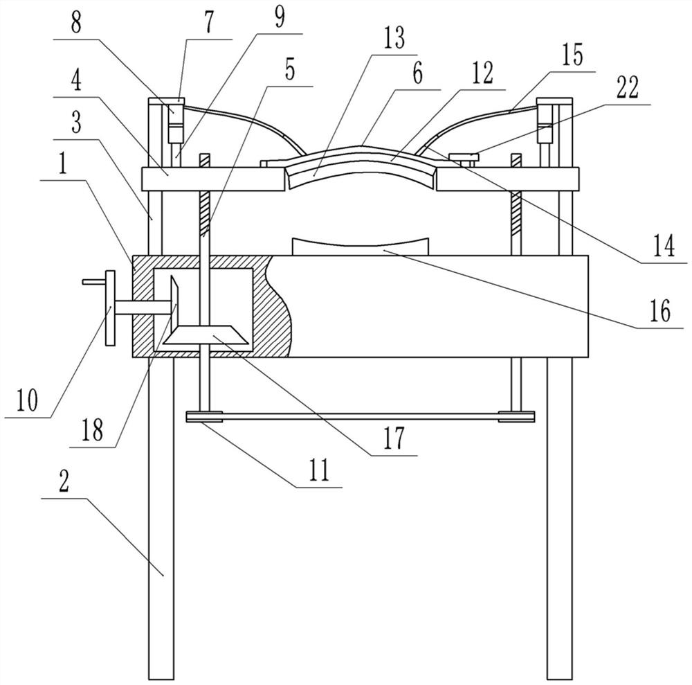
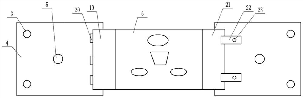
[0028] Basic as attached Figure 1-Figure 5 Shown: a postoperative facial ice compress device, including a bed body 1 and a cold compress mechanism, and four support rods 2 are welded on the bottom of the bed body 1 . figure 1 The middle cold compress mechanism is located at the right end of the bed body 1, combined with figure 2 As shown, the cold compress mechanism includes a lifting block 4, an arc-shaped pressing shell 6, an ice bag 12 and a lifting assembly for driving the lifting block 4 to reciprocate vertically. The number of lifting blocks 4 is two, and the lifting block 4 and the pressing shell 6 and the ice pack 12 are all located above the bed body 1, and the two lifting blocks 4 are respectively located figure 2 The left and right sides of the middle bed body 1 are combined image 3 As shown, the pressing shell 6 is located on the lifting block 4, the left side of the pressing shell 6 is the rotating part 19, and the rotating part 19 is connected to the liftin...
Embodiment 2
[0035] like Image 6 As shown, this embodiment is different from the lifting assembly in Embodiment 1. In this embodiment, the relevant structure for driving the screw 5 to rotate is different. Specifically: the lifting assembly includes a second turntable 29 arranged horizontally, and the bottom of the second turntable 29 A rotating shaft is welded, and the rotating shaft is connected to the middle part of the bed body 1 through a bearing. A driving pulley 30 is welded coaxially on the bottom of the rotating shaft, and a driven pulley 31 is welded coaxially on the lead screw 5. The driving pulley 30 and the driven pulley A belt is connected between the pulleys 31 .
[0036] Thus, since the second turntable 29 is positioned at the middle part of the bed body 1, so the patient lies on the bed body 1, and the patient's hand can touch the second turntable 29, so that the patient can rotate the second turntable 29, and the second turntable 29 Drive the driving pulley 30 to rotate...
Embodiment 3
[0038] In this embodiment, on the basis of Embodiment 1, a time preset reminder unit is provided on the bed body 1. Specifically, the time preset reminder unit can be an alarm clock with a timing function, so that the time preset reminder unit can be set. Set the cold compress time, when the cold compress time reaches the preset time, the time preset reminder unit will make a sound to remind the patient or medical staff that the cold compress is over and the cold compress mechanism needs to be removed to ensure that the cold compress time is controlled within a reasonable range It is beneficial to improve the practicability of the device by avoiding the cold compress for too long or too long.
PUM
 Abstract
Description
Claims
Application Information
 - R&D
- Intellectual Property
- Life Sciences
- Materials
- Tech Scout
- Unparalleled Data Quality
- Higher Quality Content
- 60% Fewer Hallucinations
Browse by: Latest US Patents, China's latest patents, Technical Efficacy Thesaurus, Application Domain, Technology Topic, Popular Technical Reports.
© 2025 PatSnap. All rights reserved.Legal|Privacy policy|Modern Slavery Act Transparency Statement|Sitemap|About US| Contact US: help@patsnap.com