Supercharge Your Innovation With Domain-Expert AI Agents!

a material hoist

A material hoist and machine body technology, applied in the direction of conveyors, conveyor objects, transportation and packaging, etc., can solve the problems of material residue, damage to the feeding belt, and insufficient technology, so as to achieve a deformable contact area and avoid material residue Effect

Active Publication Date: 2021-11-26
新沂市中振电器科技有限公司
View PDF7 Cites 0 Cited by
  • Summary
  • Abstract
  • Description
  • Claims
  • Application Information

AI Technical Summary

Problems solved by technology

[0003] Due to the imperfect technology of the existing material bucket elevators, most of the feeding hoppers and feeding belts are fixed by rivets. During the feeding and discharging process of the feeding hopper, the materials are easily left due to the rivets. As a result, the feeding is not thorough enough. In addition, this installation method greatly increases the contact area between the feeding hopper and the feeding belt. When the feeding belt is conveyed from the plane to the arc surface, the feeding hopper will generate a pulling force on the feeding belt, and the forces are mutual. , which will not only cause damage to the feeding belt, but also cause slight deformation of the feeding hopper

Method used


Image

  • a material hoist
  • a material hoist
  • a material hoist

Examples


Embodiment 1

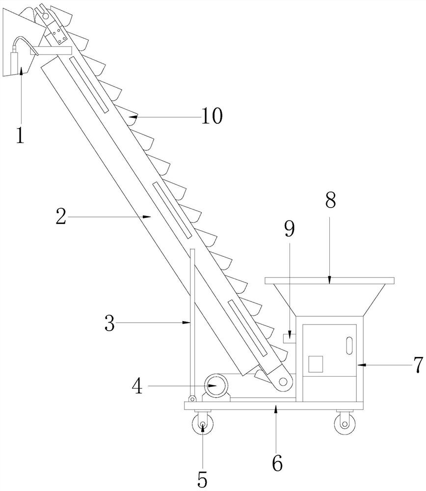
[0037] see figure 1 , the present invention provides a technical solution for a material hoist: its structure includes a material guide pipe 1, a hoist body 2, a support rod 3, a motor transmission assembly 4, a universal wheel 5, a base 6, a support frame 7, a hopper 8, The discharge port 9, the lifting bucket 10, the motor transmission assembly 4 is mechanically connected to the base 6, the motor transmission assembly 4 is connected to one end of the lifting body 2, and the other end of the lifting body 2 is provided with a material guide pipe 1. Lifting buckets 10 are evenly distributed on the lifting body 2, the lifting body 2 is connected to the base 6 through the support rod 3, the base 6 is vertically connected with a support frame 7, and a hopper is fixed on the support frame 7 8. The side of the hopper 8 facing the lifting body 2 is provided with a discharge port 9;

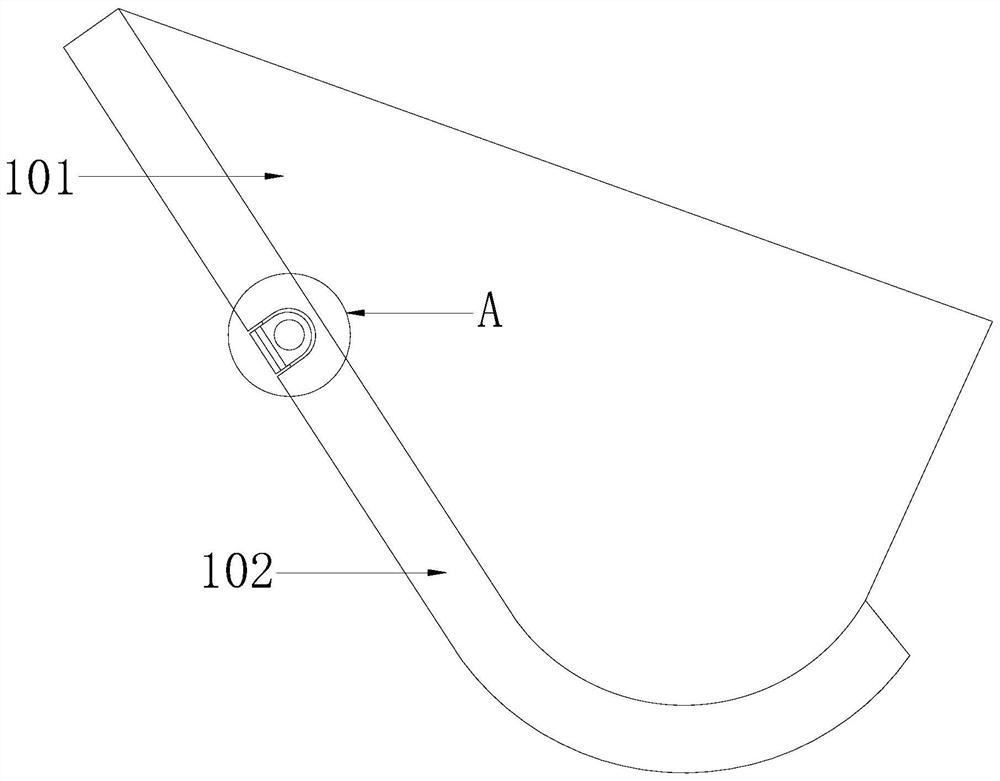
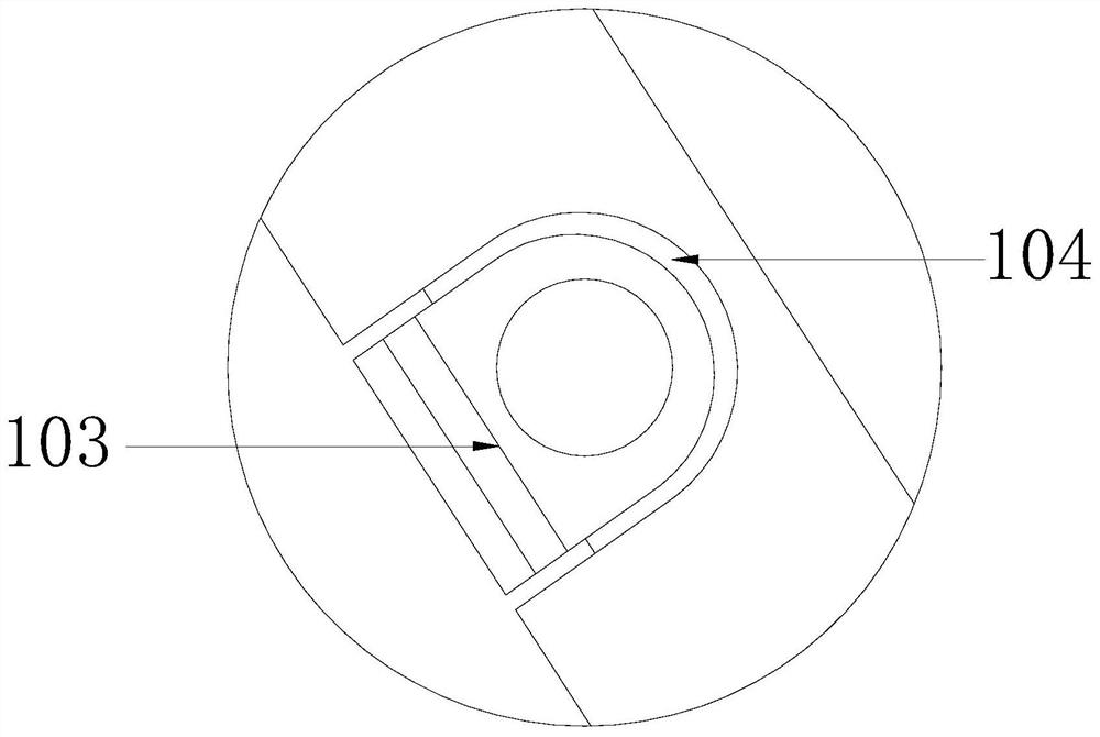
[0038] see Figure 2-3, the lifting bucket 10 includes a bucket body 101, a bottom bracket 102, a ...

Embodiment 2

[0044] see figure 1 , the present invention provides a technical solution for a material hoist: its structure includes a material guide pipe 1, a hoist body 2, a support rod 3, a motor transmission assembly 4, a universal wheel 5, a base 6, a support frame 7, a hopper 8, The discharge port 9, the lifting bucket 10, the motor transmission assembly 4 is mechanically connected to the base 6, the motor transmission assembly 4 is connected to one end of the lifting body 2, and the other end of the lifting body 2 is provided with a material guide pipe 1. Lifting buckets 10 are evenly distributed on the lifting body 2, the lifting body 2 is connected to the base 6 through the support rod 3, the base 6 is vertically connected with a support frame 7, and a hopper is fixed on the support frame 7 8. The side of the hopper 8 facing the lifting body 2 is provided with a discharge port 9;

[0045] see Figure 2-3 , the lifting bucket 10 includes a bucket body 101, a bottom bracket 102, a...


PUM


Abstract

The invention discloses a material hoist, which is realized by adopting the following technical solutions: a material hoist, the structure of which includes a material guide pipe, a hoist body, a support rod, a motor transmission assembly, a universal wheel, a base, a support frame, hopper, discharge port, lifting bucket, compared with the prior art, the beneficial effect of the present invention is that: through the combination of bucket body, bottom support, fixed support, fixed shaft, it is possible to realize the connection between the bucket body and the feeding belt. Indirect connection, in order to replace the traditional mechanical connection between the bucket body and the feeding belt directly, the rubber bottom pad is elastic, deformable and has a small contact area with the feeding belt, so that it can conform to the feeding belt when it is conveyed from a plane to an arc surface Deformation due to excessive transformation, avoiding the direct connection will cause the mutual pulling force between the feeding belt and the bucket body during excessive lifting, which can prevent the feeding belt from being damaged, help to prolong the service life of the feeding belt, and ensure the bucket body The stability of the lifting is conducive to the lifting of materials.

Description

technical field [0001] The invention relates to the technical field of automatic special machines, in particular to a material hoist. Background technique [0002] The material bucket elevator is a mechanical conveying equipment with a fixed device. It is mainly suitable for continuous lifting of powdery, granular and small pieces of materials. It has the advantages of simple structure, high conveying efficiency, high lifting height and stable operation. is widely used. [0003] Due to the imperfect technology of the existing material bucket elevators, most of the feeding hoppers and feeding belts are fixed by rivets. During the feeding and discharging process of the feeding hopper, the materials are easily left due to the rivets. As a result, the feeding is not thorough enough. In addition, this installation method greatly increases the contact area between the feeding hopper and the feeding belt. When the feeding belt is conveyed from the plane to the arc surface, the fee...

Claims


Application Information

Patent Timeline
Patent Type & Authority Patents(China)
IPC IPC(8): B65G17/12B65G41/00B65G47/18B65G47/40
CPCB65G17/126B65G41/00B65G47/18B65G47/40
Inventor 郑上平
Owner 新沂市中振电器科技有限公司
Features
  • R&D
  • Intellectual Property
  • Life Sciences
  • Materials
  • Tech Scout
  • Unparalleled Data Quality
  • Higher Quality Content
  • 60% Fewer Hallucinations
Learn More